
Speaker diaphragm and speaker using the same

a technology of diaphragm and speaker, which is applied in the direction of fiber diaphragm, transducer details, electrical transducers, etc., can solve the problems of increasing the number of components and production steps, reducing the number of production steps, and affecting the sound quality of the reinforcement ring, so as to achieve a significantly simplified production process

Inactive Publication Date: 2009-07-28
ONKYO KK
View PDF11 Cites 7 Cited by
  • Summary
  • Abstract
  • Description
  • Claims
  • Application Information

AI Technical Summary

Benefits of technology

[0007]It is an object of the present invention to provide a speaker diaphragm with which it is possible to improve the bonding strength between the diaphragm and the voice coil bobbin, thereby reducing the transmission loss and improving the S / N ratio.
[0010]Since one end of the voice coil bobbin is bonded to the bobbin-receiving portion, the end of the voice coil bobbin is fixed, whereby it is possible to prevent the end of the voice coil bobbin from vibrating in the radial direction. Therefore, it is possible to prevent the voice coil bobbin as a whole from vibrating (bending) in the radial direction, thereby preventing unnecessary sound from being generated from the voice coil bobbin itself. This can improve the S / N ratio. Moreover, this facilitates the positioning of the voice coil bobbin when attaching the voice coil bobbin to the diaphragm. Moreover, since the voice coil bobbin and the first diaphragm portion (and the second diaphragm portion) are firmly bonded to each other, it is possible to accurately transmit the vibration of the voice coil bobbin to the diaphragm and it is possible to prevent the diaphragm from being deformed. With the bobbin-receiving portion protruding from the back side of the diaphragm, it is no longer necessary to form a plurality of bends in the diaphragm as in Patent Document 1. Specifically, the first extension and the second extension are provided extending from the first diaphragm portion and the second diaphragm portion, respectively. Therefore, the first diaphragm portion and the second diaphragm portion have a very high durability. Moreover, the vibration of the voice coil bobbin is transmitted to the first diaphragm portion and the second diaphragm portion without being reflected. Therefore, it is possible to quite desirably prevent the transmission loss of vibration.
[0012]While the substrate is impregnated with the thermosetting resin to form the first diaphragm portion (and the second diaphragm portion), the bobbin-receiving portion can be formed by the same thermosetting resin. Thus, the production process is significantly simplified. Moreover, the bobbin-receiving portion, which is made only of the thermosetting resin, has a higher internal loss than that of the first diaphragm portion (and the second diaphragm portion), which are obtained by impregnating the substrate with the thermosetting resin. Therefore, the vibration of the voice coil bobbin in the radial direction is attenuated by the bobbin-receiving portion having a high internal loss and is less transmitted to the first diaphragm portion (and the second diaphragm portion). Thus, it is possible to prevent the generation of distortion.
[0014]An unsaturated polyester resin has a high cure rate and a low cure temperature, thus facilitating the production process, and it is possible with an unsaturated polyester to obtain the first and second diaphragm portions and the bobbin-receiving portion each having a desirable internal loss.
[0016]In still another aspect of the present invention, there is provided a method for producing a speaker diaphragm. The production method includes the steps of: impregnating portions of a substrate to be a first diaphragm portion and a second diaphragm portion with a thermosetting resin; supplying the thermosetting resin to a portion of a die for forming a bobbin-receiving portion to which one end of a voice coil bobbin is bonded; and curing the thermosetting resin, whereby a portion of the thermosetting resin with which the first diaphragm portion and the second diaphragm portion are impregnated forms the first diaphragm portion and the second diaphragm portion, while another portion of the thermosetting resin supplied to the portion of the die for forming the bobbin-receiving portion forms the bobbin-receiving portion. Thus, the production process is significantly simplified.

Problems solved by technology

Thus, the vibration of the bobbin 602 is reflected at the bends A1 to A7, thus causing a transmission loss of vibration.
However, the provision of the reinforcement ring adds to the number of components and the number of production steps.
Moreover, the reinforcement ring has an adverse influence on the sound quality.

Method used


Image

  • Speaker diaphragm and speaker using the same
  • Speaker diaphragm and speaker using the same
  • Speaker diaphragm and speaker using the same

Examples


Embodiment Construction

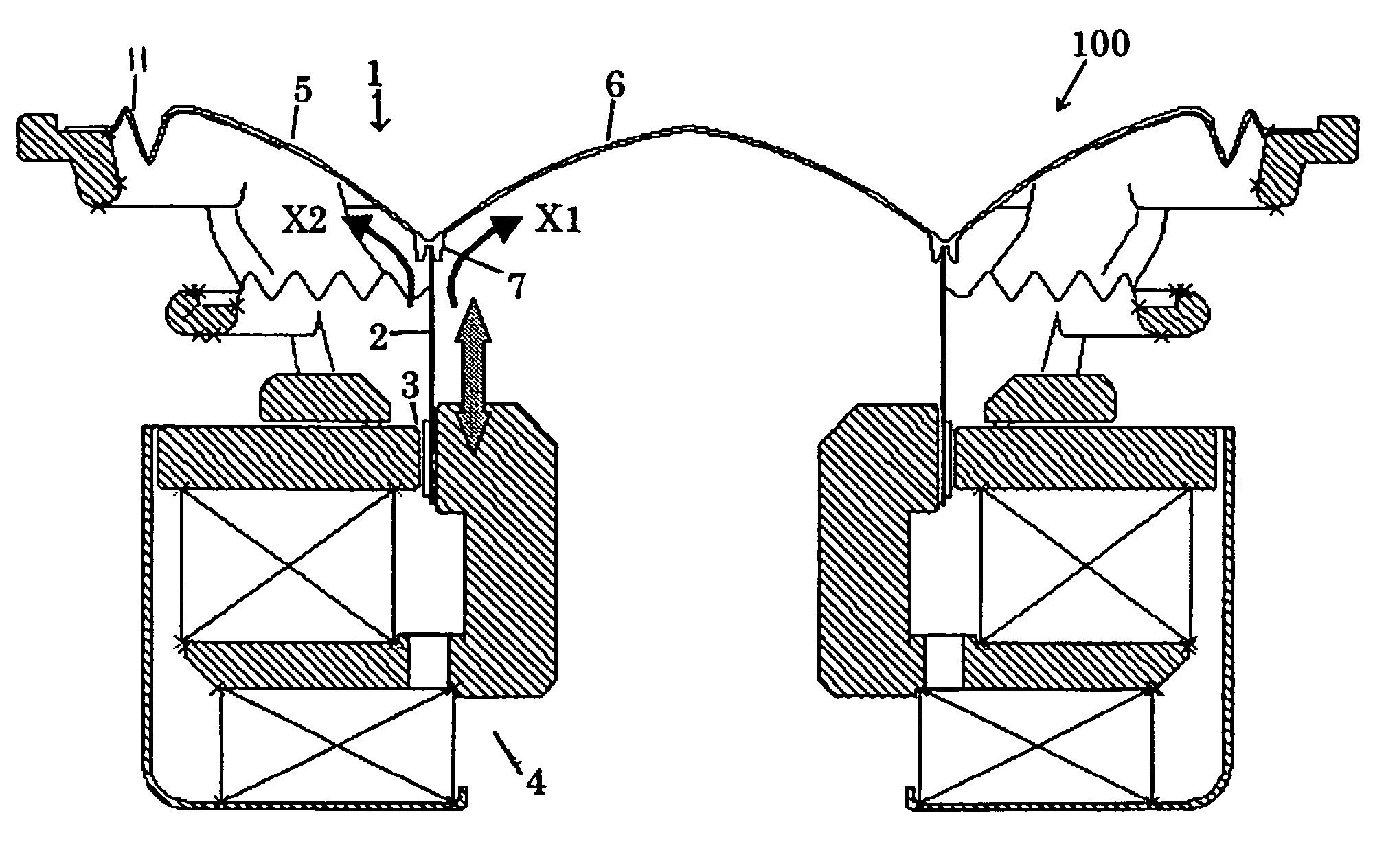
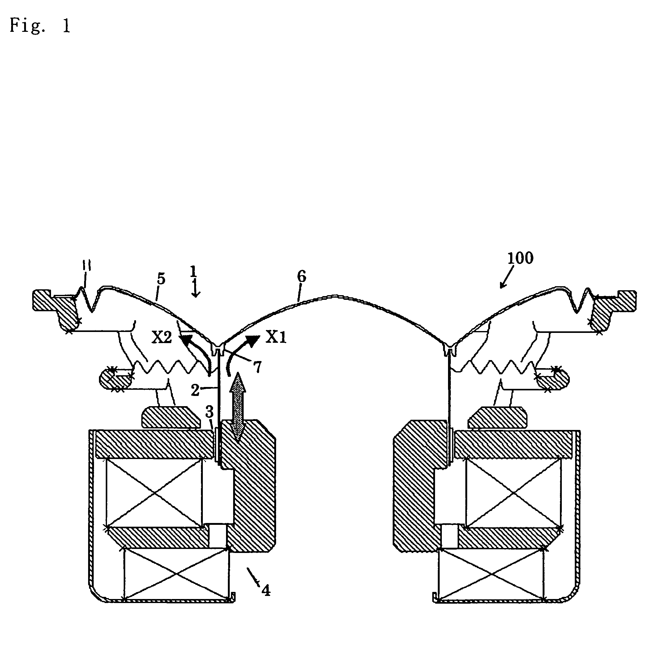
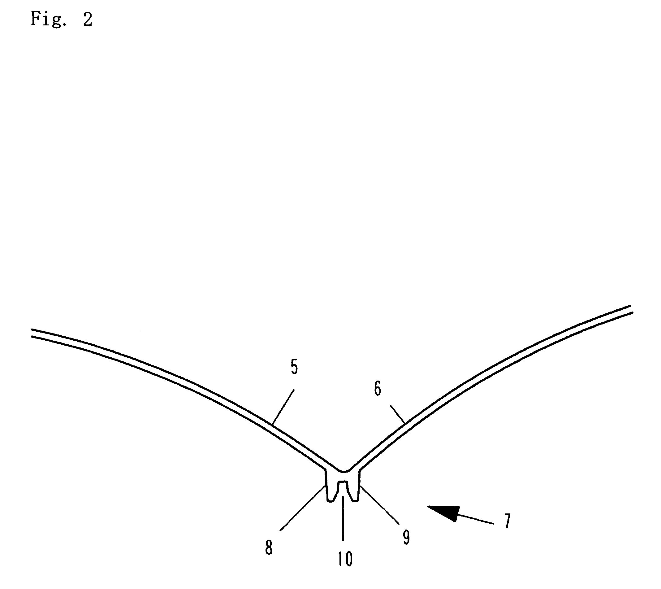
[0023]While a preferred embodiment of the present invention will now be described with reference to the drawings, it is understood that the present invention is not limited thereto. FIG. 1 is a schematic cross-sectional view showing a speaker 100 according to a preferred embodiment of the present invention. FIG. 2 is an enlarged view showing an important part of a diaphragm 1 of the speaker 100. The speaker 100 includes the diaphragm 1, a voice coil bobbin 2 bonded to the diaphragm 1, and a voice coil 3 wound around a lower portion of the voice coil bobbin 2. The voice coil 3 is placed in the magnetic gap of a magnetic circuit 4, and is displaced in the magnetic gap according to the input signal to drive the diaphragm 1.

[0024]The diaphragm 1 includes a first diaphragm portion 5, and a second diaphragm portion 6 integrally molded with the first diaphragm portion 5. As necessary, the diaphragm 1 includes an edge portion 11 integrally molded with the first diaphragm portion 5 (the edge...


PUM


Abstract

A speaker diaphragm 1 includes a first diaphragm portion 5, a second diaphragm portion 6 integrally molded with the first diaphragm portion 5, and a bobbin-receiving portion 7 protruding from a back side of a connecting portion between the first diaphragm portion 5 and the second diaphragm portion 6, with one end of a voice coil bobbin 2 being bonded to the bobbin-receiving portion 7. The bobbin-receiving portion 7 includes a first extension 8 extending backwards from the first diaphragm portion 5 and a second extension 9 extending backwards from the second diaphragm portion 6. A bobbin-receiving groove 10 is defined between the first extension 8 and the second extension 9. The voice coil bobbin 2 is inserted in and bonded to the bobbin-receiving groove 10.

Description

BACKGROUND OF THE INVENTION[0001]1. Field of the Invention[0002]The present invention relates to a speaker diaphragm, and more particularly to a speaker diaphragm to which a voice coil bobbin can be attached with an improved bonding strength.[0003]2. Description of the Related Art[0004]FIG. 5 is a cross-sectional view showing a conventional speaker 500. The speaker 500 includes a bobbin 502, and a diaphragm 501 bonded to the outer surface of the bobbin 502. The outer surface of the bobbin 502 has a plain cylindrical shape (curved surface), and the adhesion between the bobbin 502 and the diaphragm 501 is dependent solely on the bonding strength of the adhesive used therebetween. Therefore, the vibration of the bobbin 502 cannot accurately be transmitted to the diaphragm 501 (some transmission loss occurs). The diaphragm 501 may come off the bobbin 502 due to deformation of the diaphragm 501 and / or an insufficient bonding strength. The vibration of the bobbin 502 produced according to...

Claims


Application Information

Patent Timeline
Patent Type & Authority Patents(United States)
IPC IPC(8): H04R25/00
CPCH04R9/045H04R31/003H04R31/006H04R2307/029H04R2307/025
Inventor ONO, YUSHIHISAMOTO, SADATOSHIINOUE, TAKERU
Owner ONKYO KK
Learn More