Grain drying aeration system

a grain drying and aeration system technology, applied in drying, furnace types, light and heating equipment, etc., can solve the problems of aeration unit, structural failure, damp grain in the center and top of the bin,

Inactive Publication Date: 2009-08-04
WOODHAVEN CAPITAL
View PDF181 Cites 41 Cited by
  • Summary
  • Abstract
  • Description
  • Claims
  • Application Information

AI Technical Summary

Problems solved by technology

Such aeration systems dry grain from the bottom up, which often leaves the grain in the center and top of the bin damp.
A significant problem with vertical aeration units is structural failure during unloading of the storage bin.
Thus, an aeration unit within the grain bin must be able to resist these forces under a variety of conditions, or be subject to structural failure.
However, the failure rate is high when vertical units are installed in a steep cone hopper bin where mass flow is present.
The structural failure arises, since the inside and outside walls of the hollow vertical tube do not have sufficient strength to resist the vertical forces that are created from the boundary layer drag during unloading.
While the light gauge sheet metal used in conventional vertical aeration systems may survive the vertical forces as long as the unit remains absolutely vertical, these units are also subject to relatively high horizontal and bending forces during unloading.
The physical weight of the grain against the walls of the vertical tube can create deformations that destroy the vertical alignment of the light gauge walls, and significantly reduce the load carrying capacity of the tube.
Then, the walls are crushed and the structure fails.
Another problem with vertical bin aeration systems is the inability to retrofit such systems into existing bins.
Typically, the sheet metal walls which form the cylindrical tube are factory assembled using rivets and self-drilled sheet metal screws, which are not reasonably feasible to field assembly within a bin.

Method used


Image

  • Grain drying aeration system
  • Grain drying aeration system
  • Grain drying aeration system

Examples


Embodiment Construction

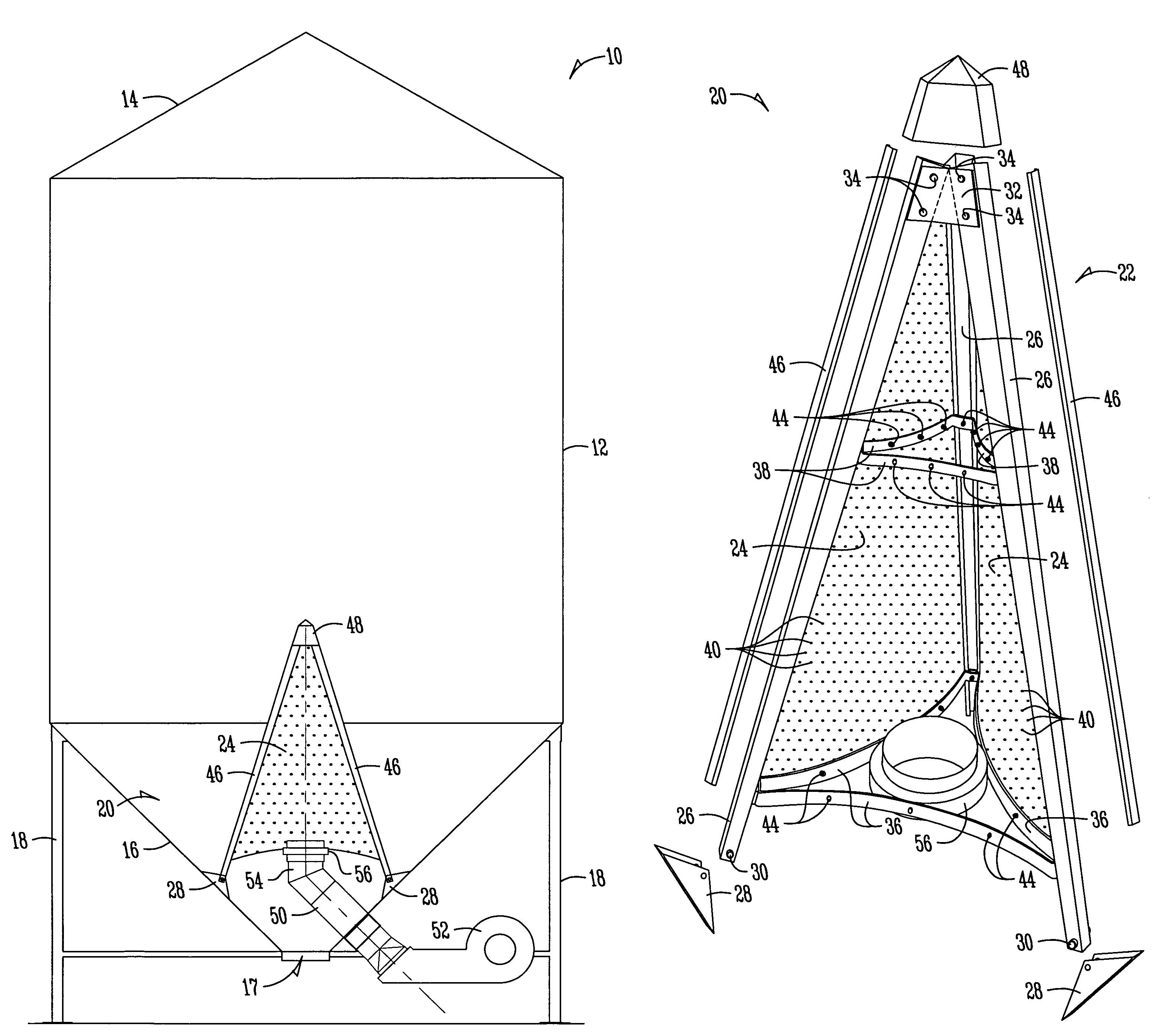
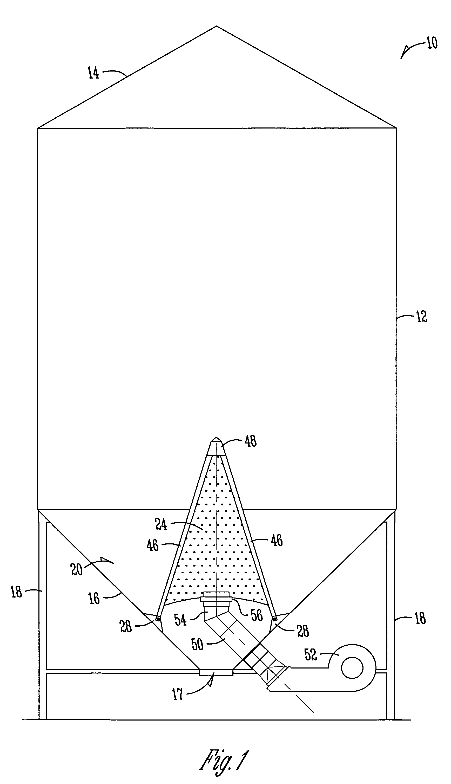
[0018]FIG. 1 shows a grain bin 10, having a side wall 12, a top 14, a bottom hopper 16 and support legs 18. The general structure of the grain bin 10 is convention, and does not constitute part of the present invention. It is understood that the slope of the bottom hopper 16 will vary from that shown in FIG. 1, for example from 40-55°. The bottom hopper 16 of the bin 10 includes a centrally disposed outlet opening 17 through which grain is discharged. A gate (not shown) is moveable between open and closed positions with respect to the outlet opening 17.

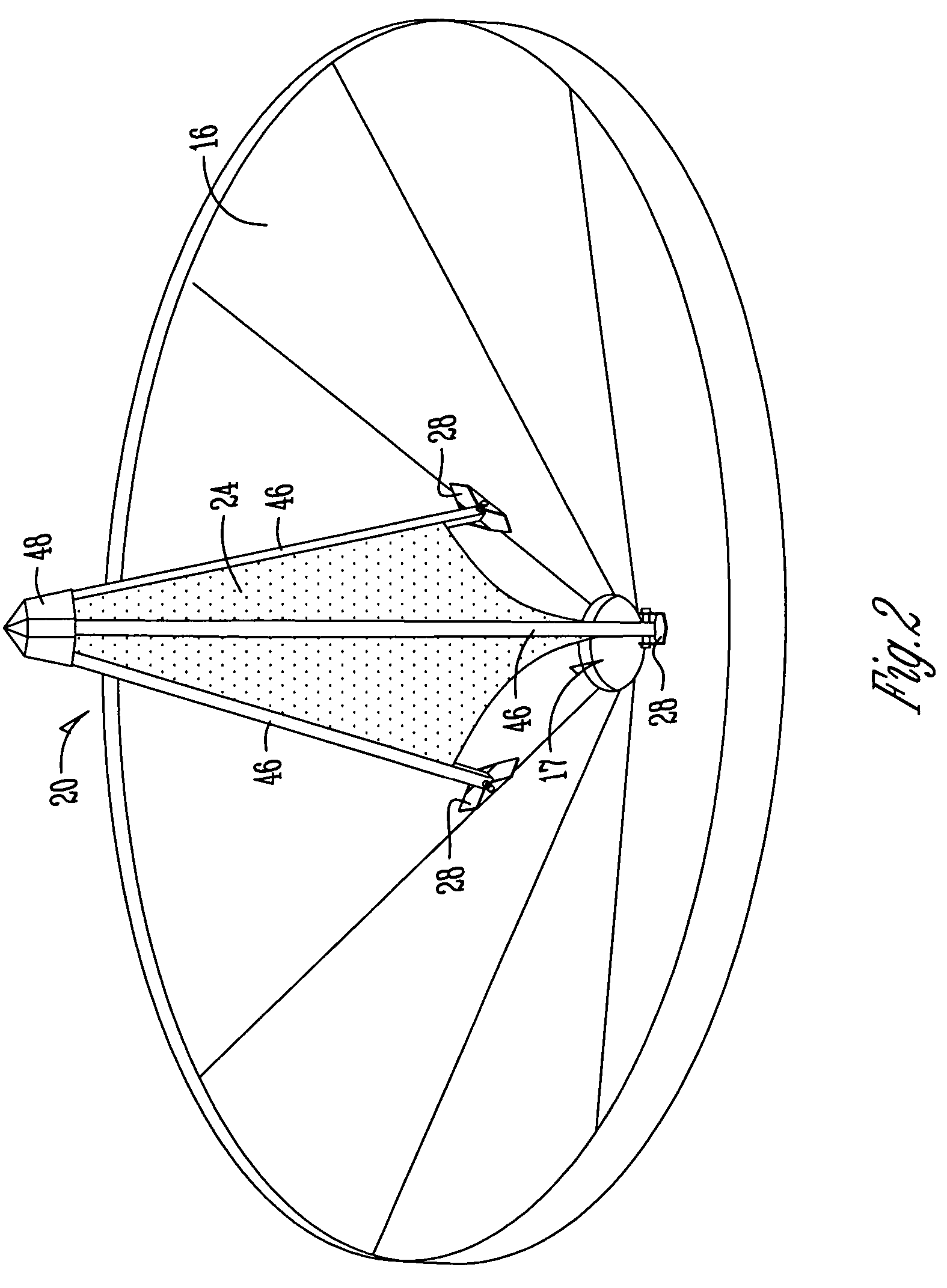
[0019]The present invention is directed towards an improved vertical aeration system 20 having a pyramid frame 22 and concave walls 24. FIG. 3 shows the components of the aeration system 20, with one of the walls 24 removed for clarity. The frame 24 includes legs 26 with upper and lower ends. A base plate 28 is pivotally attached to the lower end of each leg 26 using any convenient connector, such as a bolt or pin (not shown) extendin...


PUM


Abstract

An improved vertical aeration system is provided for a grain bin having a sloped hopper bottom with a discharge opening. A pyramid frame includes legs with lower ends attachable to the hopper bottom. Concave perforated walls are attached to the legs. Braces extending between the legs provide structural support for the walls. An air duct extends upwardly and centrally into the interior of the frame, to supply air into the aeration system for flow outwardly through the perforated walls.

Description

BACKGROUND OF THE INVENTION[0001]Grain bins for storing various types of grain commonly include aeration systems to enhance drying of the grain within the bin. One type of aeration system comprises a perforated floor in the bin through which air is forced. Such aeration systems dry grain from the bottom up, which often leaves the grain in the center and top of the bin damp. Another type of aeration system is one or more horizontal tubes extending through the bin with holes in the tubes to provide drying air.[0002]Another aeration system utilizes a centrally located vertical aeration tube extending upwardly from the bottom of the bin, with holes in the cylindrical tube wall to provide drying air to the grain in the bin. Such vertical tube aeration systems are typically used in grain bins having a sloped hopper bottom with a central discharge opening with a gate moveable between open and closed positions. One type of vertical tube aeration system known as the Grain Guard Rocket has a ...

Claims


Application Information

Patent Timeline
Patent Type & Authority Patents(United States)
IPC IPC(8): F26B19/00
CPCF26B9/103F26B2200/06
Inventor PIERSON, KENMACDONALD, BRIANPENNER, JOHN
Owner WOODHAVEN CAPITAL
Why Eureka
Try Eureka