Ultraviolet germicidal lamp base and socket

a technology of lamp base and socket, which is applied in the direction of tubes with electrostatic control, coupling device connections, instruments, etc., can solve the problems of requiring relatively complicated mounting hardware and additional switches to prevent lamp operation, and achieve direct visual confirmation of lamp operation , prevent the possibility of ultraviolet lamp remaining

Active Publication Date: 2009-08-04
LIGHT SOURCES INC
View PDF39 Cites 55 Cited by
  • Summary
  • Abstract
  • Description
  • Claims
  • Application Information

AI Technical Summary

Benefits of technology

[0010]It is an advantage of the present invention that the ultraviolet lamp is pushed directly into a socket engaging the contact pins.
[0011]It is an advantage of the present invention that upon removing the ultraviolet lamp from the fluid duct and socket the contact pins are disengaged, automatically removing power from the ultraviolet lamp, preventing the possibility of the ultraviolet lamp remaining on while unshielded by the duct.
[0012]It is another advantage of the present invention that direct visual confirmation of operation of the lamp can be made even when the lamp is completely enclosed in a duct.
[0013]It is a feature of the present invention that a contact pin shield extends from the base cap protecting the contact pins from inadvertent electrical contact or damage to the pins.
[0014]It is a feature of the present invention that the contact pins are placed adjacent the sides of the lamp and a distal end extends toward an opposing end of the lamp.
[0015]It is another feature of the present invention that a window is placed in the base cap.

Problems solved by technology

While these prior devices have aided in the quick installation and safe operation of an ultraviolet germicide gas discharge lamp used to disinfect fluids, they often required relatively complicated mounting hardware and additional switches to prevent operation of the lamp upon removal from the fluid flowing in a duct or conduit.

Method used


Image

  • Ultraviolet germicidal lamp base and socket
  • Ultraviolet germicidal lamp base and socket
  • Ultraviolet germicidal lamp base and socket

Examples


Embodiment Construction

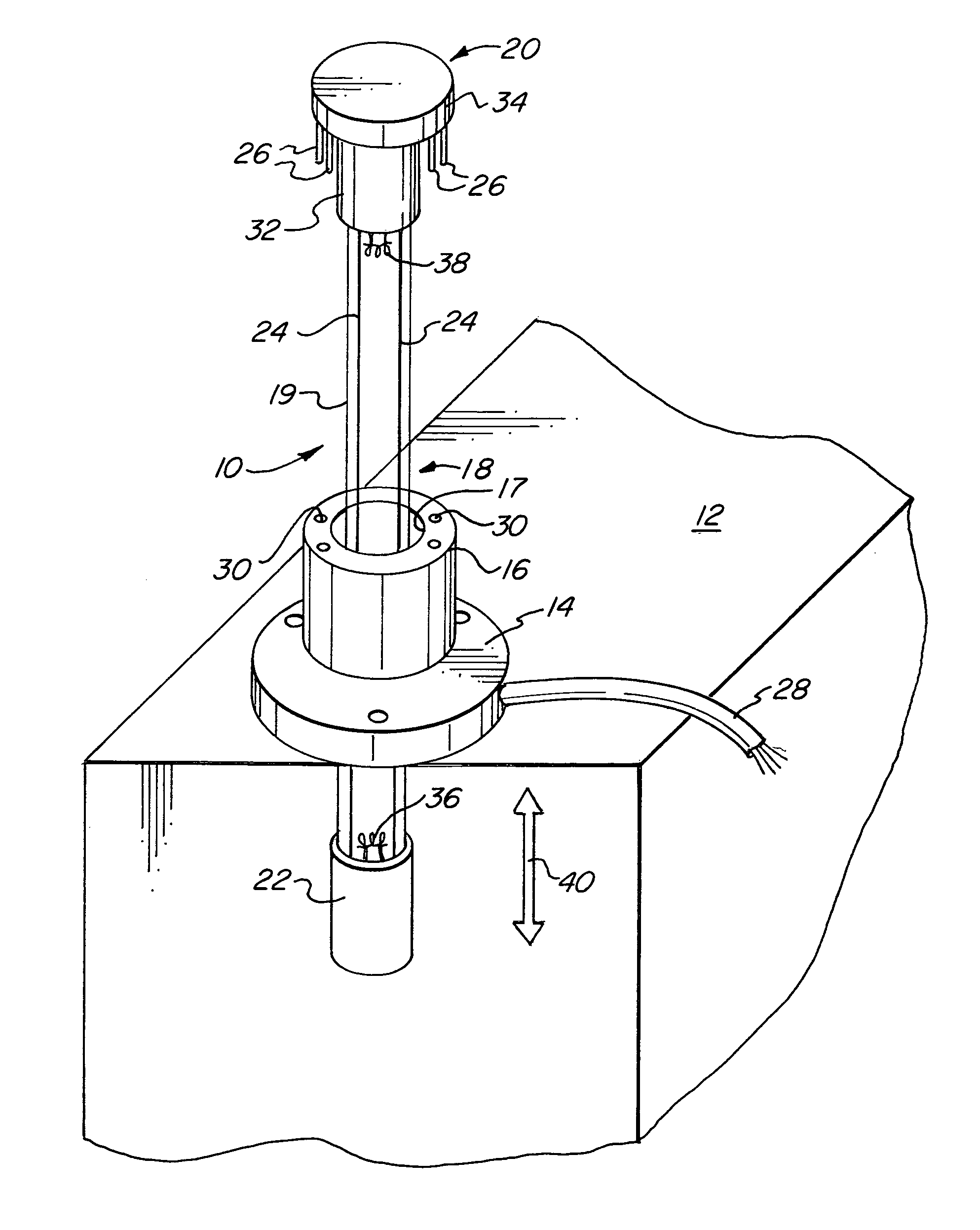
[0023]FIG. 1 illustrates an ultraviolet lamp fluid duct germicidal system 10. A fluid duct 12 has an opening therein on which a mounting flange 14 is placed. The fluid duct 12 may contain air or other gas or liquid such as water to be disinfected. The mounting flange 14 has a socket 16. The socket 16 has a plurality of contact pin holes 30 therein. A hole 17 is placed through the socket 16 and flange 14 and opens into the fluid duct 12. A lamp 18 is placed within the socket 16 and extends into the interior of the fluid duct 12. The lamp 18 is preferably an ultraviolet gas discharge or fluorescent lamp such as is commonly used in germicidal applications.

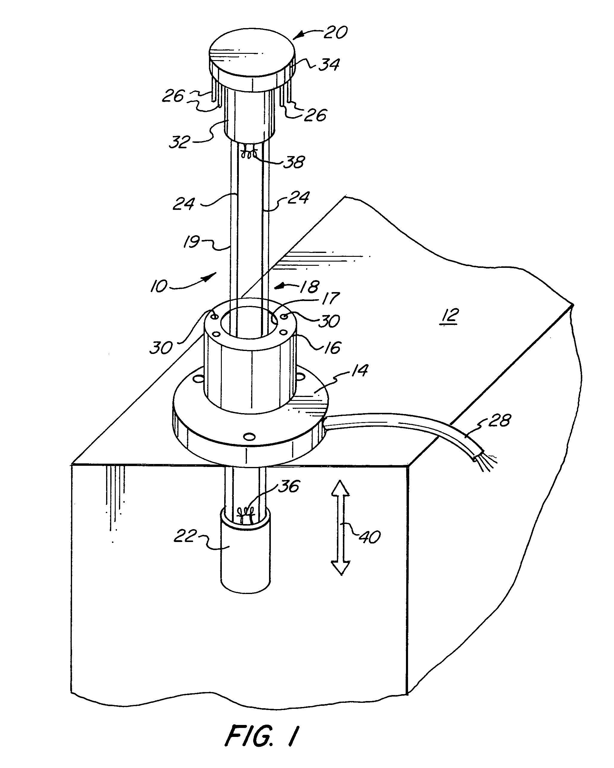
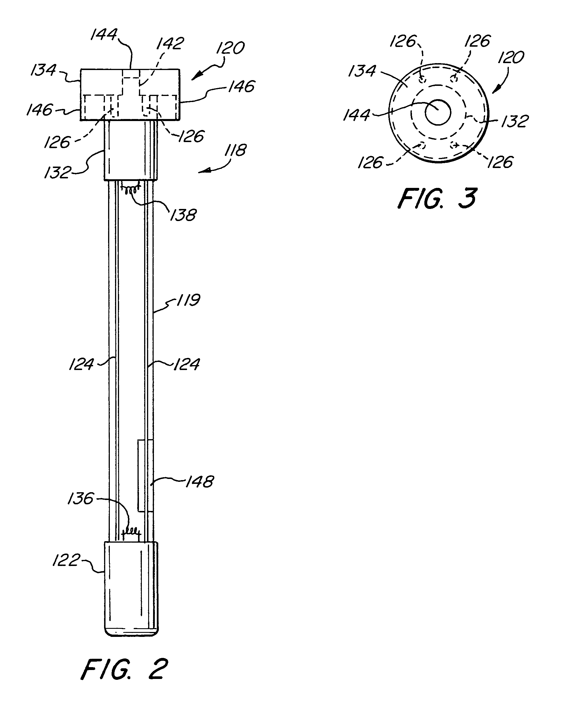
[0024]The lamp 18 has a base cap 20 on one end and an end cap 22 on the other. The base cap 20 comprises a disk cap 34 and a cylindrical base 32. The disk cap 34 extends radially sufficiently beyond the exterior surface of the lamp 18 so as to permit contact pins 26 to have the distal ends thereof extending downward towards the opposi...


PUM


Abstract

An ultraviolet gas discharge lamp having contact pins extending downward from a base cap toward an opposing end. The lamp is placed within a conduit or duct for disinfecting air or water flowing within the conduit. The reverse contact pins that extend toward the opposing end mate with contact holes in a socket attached to the conduit through which the lamp is inserted. The lamp is only energized when the lamp is fully inserted into the duct and is de-energized upon removing the lamp from the duct. A shield protects the pins. A window may be place in the base cap so as to visually confirm that the lamp is energized and radiating. A key and mating receiver may be used on the base cap and the socket so as to prevent accidental insertion of an inappropriate lamp.

Description

FIELD OF THE INVENTION[0001]The present invention relates in general to a lamp base and socket and more specifically to a lamp base and socket for inserting an ultraviolet lamp into an air or fluid duct for germicidal purposes.BACKGROUND OF THE INVENTION[0002]Many germicidal applications use ultraviolet gas discharge lamps. Ultraviolet gas discharge lamps are often placed in containers or ducts that contain a fluid, such as air or water. The ultraviolet radiation emitted from the ultraviolet gas discharge lamp has a germicidal effect destroying germs, viruses, and bacteria disinfecting the fluid. Often the ultraviolet gas discharge lamp is placed directly within the air flow in a conduit. In applications involving the disinfecting of a liquid, often a protective glass sleeve is used to surround the ultraviolet gas discharge lamp.[0003]The ultraviolet gas discharge lamp should be easily installed, and installed so as to prevent ultraviolet radiation from escaping from the conduit or ...

Claims


Application Information

Patent Timeline
Patent Type & Authority Patents(United States)
IPC IPC(8): H01J5/48H01J5/50H01R13/52
CPCA61L9/20C02F1/325H01J5/62H01J5/50H01J5/54C02F2201/004C02F2201/3228Y10S439/934
Inventor CIANCANELLI, GINO
Owner LIGHT SOURCES INC
Why Eureka
Try Eureka