
Omni-directional imaging and illumination assembly

a technology of omni-directional imaging and assembly, applied in the field of omni-directional imaging and illumination, can solve the problems of limited performance, relative complexity, frequent alignment, etc., and achieve the effect of preventing glare, preventing glare, and preventing glar

Inactive Publication Date: 2009-08-04
MISTRAL DETECTION LTD
View PDF23 Cites 23 Cited by
  • Summary
  • Abstract
  • Description
  • Claims
  • Application Information

AI Technical Summary

Benefits of technology

"The present invention provides an omni-directional imaging assembly that can capture images from multiple directions simultaneously. The assembly includes an omni-directional lens with a vertical axis of symmetry, an upper surface, a transparent perimeter surface, a lower convex surface, and a transparent circular surface maintained in the lower convex surface. The lens has a reflective material on its interior surface to reflect rays from the inner side of the lens. The assembly can also include an illumination source to provide omni-directional illumination. The technical effects of the invention include improved image capture and illumination capabilities."

Problems solved by technology

Military systems will also benefit from the ability to view an omni-directional scene and so will most systems based on image sensing, whose performance is currently limited by the limited aperture provided by their optical lenses.
The main disadvantage of the above mentioned prior art methods is their relative complexity.
Some of the prior art methods necessitate moving / rotating mechanisms, require frequent alignment and very often turn out to be maintenance-intensive.

Method used


Image

  • Omni-directional imaging and illumination assembly
  • Omni-directional imaging and illumination assembly
  • Omni-directional imaging and illumination assembly

Examples


Embodiment Construction

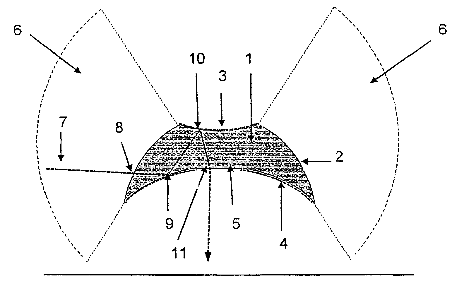
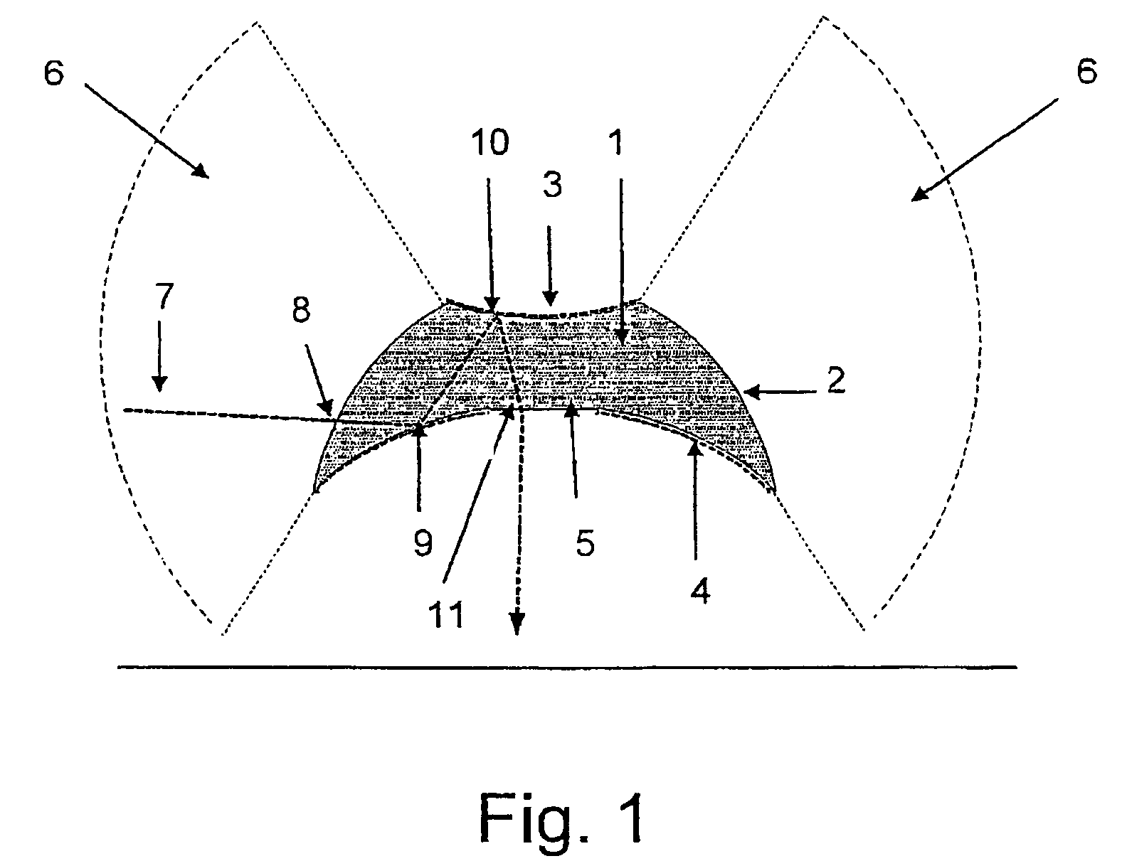
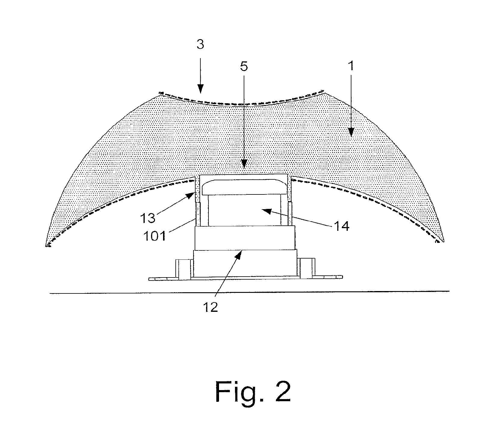
[0058]A first embodiment of the present invention provides a panoramic imaging assembly based on a unique optical block. The optical block is designed to collect light rays from a surrounding 360 degrees field of view and reflect them towards an image capture device located coaxially with it. The optical block is designed to have a transparent upper surface coated with reflective material on its exterior side, a perimeter transparent surface and a lower convex transparent surface, which in some embodiments is coated with reflective material on its exterior side. A transparent circular surface is maintained at the center of the lower convex transparent surface and is designed to allow light rays that arrive from the direction of the upper surface to exit the optical block and reach the image capture device. It is stressed that the exact structure of the optical block and the exact formulas describing its curves are subject to precise optical design. Proper optical design will preserv...


PUM


Abstract

In a first aspect, the present invention provides an omni-directional imaging assembly. In the preferred embodiment the assembly of the invention comprises a solid omni-directional lens comprising a vertical axis of symmetry; an upper surface, at least part of which is capable of reflecting rays that arrive from the inner side of the omni-directional lens; a transparent perimeter surface; a lower convex surface, at least part of which is capable of reflecting rays that arrive from the direction of the perimeter surface; and a transparent circular surface maintained in the lower convex surface around the vertical axis of symmetry. The light rays from a first 360 degrees, panoramic, scene are refracted by the transparent perimeter surface, are then reflected by the lower convex surface towards the upper surface, and then reflected by the upper surface towards the transparent circular surface, where they are refracted and exit the omni-directional lens. In a second aspect the omni-directional imaging assembly of the invention can be combined with an illumination source to simultaneously provide both omni-directional imaging and omni-directional illumination. Also described are embodiments of the invention that comprise image capturing devices, embodiments that enable simultaneous imaging of the first scene and a second scene, and embodiments that are adapted to the requirements of endoscopic imaging.

Description

FIELD OF THE INVENTION[0001]The present invention relates to the field of omni directional imaging and illumination. More specifically, it relates to optical structures that enable the coverage and illumination of a panoramic or nearly spherical field of view, suitable for video or still imaging in both well-lit environments as well as dark environments.BACKGROUND OF THE INVENTION[0002]The use of imaging equipment has penetrated, over the years, into almost every field and has become an essential aid for accomplishing a variety of tasks. Imaging equipment is used in a wide range of security systems, to monitor sensitive locations and facilities, and to provide a reliable and cost-effective solution for perimeter security. An additional use for imaging equipment is in the military, where image-based systems are used for reconnaissance gathering, enhanced situational awareness, automatic navigation and for many additional human-operated as well as automated systems.[0003]In the medica...

Claims


Application Information

Patent Timeline
Patent Type & Authority Patents(United States)
IPC IPC(8): G02B13/06H04N15/00
CPCG02B13/06G03B37/06G03B2215/0582
Inventor GAL, EHUDLITEYGA, GENNADIYGRAISMAN, GIL
Owner MISTRAL DETECTION LTD
Learn More