Probe for use in measuring a biological signal and biological signal measuring system incorporating the probe

a technology for biological signals and probes, which is applied in the field of biological signal measuring systems incorporating probes, can solve the problems of unreliable diagnosis, inability to know whether the subject's fingernail accurately contacts the light source of conventional probes, etc., and achieves the effects of increasing the signal-to-noise ratio, reducing noise, and improving reliability

Active Publication Date: 2009-08-11
SAMSUNG ELECTRONICS CO LTD
View PDF16 Cites 29 Cited by
  • Summary
  • Abstract
  • Description
  • Claims
  • Application Information

AI Technical Summary

Benefits of technology

[0017]When using the probe and the biological signal measuring system according to the present invention described above, it is possible to minimize the generation of noise arising from the movem...

Problems solved by technology

However, it may not be known whether the subject's fingernail accurately contacts a light source of the conventional probe.
Although the fingernail may contact the light source, noise components from external...

Method used


Image

  • Probe for use in measuring a biological signal and biological signal measuring system incorporating the probe
  • Probe for use in measuring a biological signal and biological signal measuring system incorporating the probe
  • Probe for use in measuring a biological signal and biological signal measuring system incorporating the probe

Examples


first embodiment

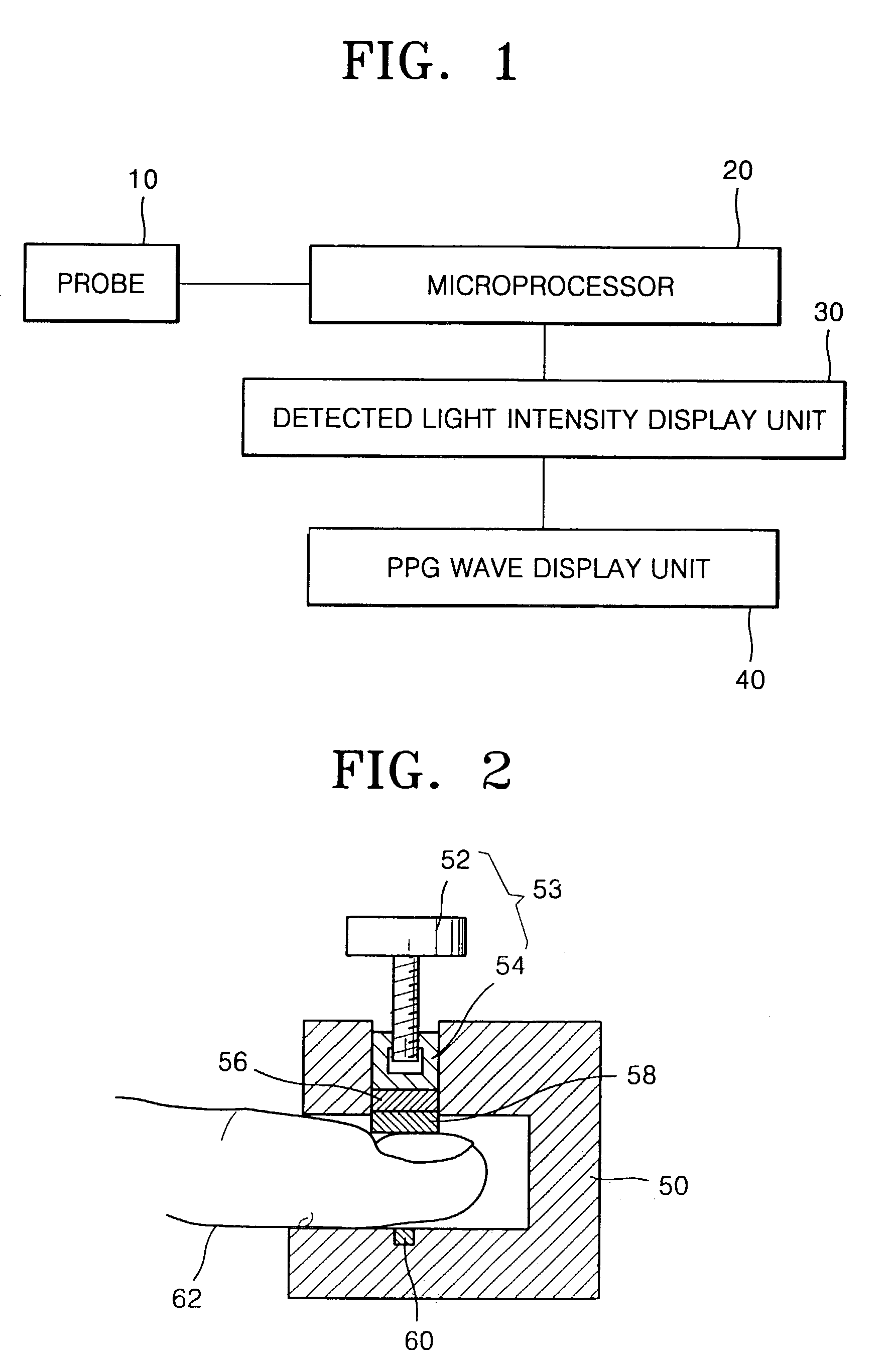
[0037]Referring to FIG. 2, the probe 10 includes a body 50 having a space into which an object 62, for example, a finger, is inserted, a light source unit 58, and a photodetector unit 60. The body 50 consists of parallel upper and lower portions and a vertical portion connecting the upper and lower portions. The light source unit 58, which includes a light source, such as a light emitting diode (LED), for emitting measurement light near the cuticle of the finger, is positioned at a predetermined location on the upper horizontal portion of the body 50. The light source unit 58 may protrude from the upper horizontal portion of the body toward the photodetector unit 60. It is preferable that the light source unit 58 protrudes to such a degree that a subject becomes aware that his / her fingernail has contacted the light source unit 58 when the object 62, i.e., the finger, is inserted into the probe 10. i.e., between the upper and lower horizontal portions of the body 50. The photodetecto...

fourth embodiment

[0050]FIGS. 7 and 8 illustrate a probe with a pressure application unit that applies pressure to a measurement site of an object using a weight, before and after an object is inserted into the probe.

[0051]Referring to FIGS. 7 and 8, an upper horizontal portion of a body 110 of the probe has a through hole 114 along which a light source unit 118 and a heat dissipating plate 116 are moved up and down. A fourth embodiment of the pressure application unit 112 is connected to the heat dissipating plate 116 via the through hole 114. The fourth embodiment of the pressure application unit 112 is a structure with a vertical portion having a first end connected to the heat dissipating plate 116 and a second end, opposite to the first end, extending vertically out of the through hole 114 above the upper horizontal portion of the body 110, and a horizontal portion connected to the second end of the vertical portion, the horizontal portion being parallel to the upper horizontal portion of the bo...


PUM


Abstract

A probe for use in photoplethysmographic (PPG) measurement includes a light source unit including a light source that contacts a predetermined site of an object and emits light onto the predetermined site, a photodetector unit positioned facing the light source unit to receive the light emitted from the light source unit and transmitted through the object, a body having a space for receiving the object and in which the light source unit and the photodetector unit are positioned in a same optical axis, and a pressure application unit coupled to the body for applying a pressure to the object via the light source unit. A biological signal measuring system includes the above probe, a controller for controlling operations of the probe and for recording and analyzing signals output from the probe, a detected light intensity display unit for displaying an intensity of detected light, and a biological signal display unit.

Description

BACKGROUND OF THE INVENTION[0001]1. Field of the Invention[0002]The present invention relates to a probe for use in measuring a biological signal and a biological signal measuring system incorporating the probe.[0003]2. Description of the Related Art[0004]Pulsation (i.e., pulse) and blood pressure, like human metabolism, vary among individuals. In addition, blood components, blood volume, and pulsation intensity vary at measuring sites of a subject, and even at the same measuring site depending on when the measurement is performed and the subject's physical state. Accordingly, reliable biological signal measuring devices with the ability to provide accurate biological information on a subject are required. Such a measuring device may be a probe that provides information, such as a photoplethysmogram.[0005]Biological signal measurement sites should not cause stress to a patient subjected to a biological signal measurement, but should allow measurement of a faint biological signal fro...

Claims


Application Information

Patent Timeline
IPC IPC(8): A61B5/00A61B5/022
CPCA61B5/02241A61B5/14552A61B5/6843A61B5/6838A61B5/6826A61B5/00
Inventor YEO, HYUNG-SOKKIM, HONG-SIGYOON, GIL-WON
Owner SAMSUNG ELECTRONICS CO LTD
Why Eureka
Try Eureka