Method for making light emitting diode

a technology of light-emitting diodes and methods, applied in the direction of refractors, display means, lighting and heating apparatus, etc., can solve the problems of low optical uniformity, poor purity of white light, and high energy consumption

Inactive Publication Date: 2009-08-11
HON HAI PRECISION IND CO LTD
View PDF3 Cites 70 Cited by
  • Summary
  • Abstract
  • Description
  • Claims
  • Application Information

AI Technical Summary

Problems solved by technology

Disadvantages of a CCFL include high energy consumption, low optical uniformity, and poor purity of white light.
In addition, after being repeatedly used over time, a brightness of the CCFL becomes degraded and a color of light emitted by the CCFL tends to shift.
Therefore, using a CCFL cannot satisfy the requirements for a high quality color liquid crystal display.
However, precisely positioning the transparent plate 15 according to the LEDs 12 can be very problematic and troublesome, due to the small size of the LEDs 12.
In addition, the transparent plate 13 makes the backlight module 10 rather heavy, and adds to manufacturing costs.

Method used


Image

  • Method for making light emitting diode
  • Method for making light emitting diode
  • Method for making light emitting diode

Examples


Embodiment Construction

[0017]Reference will now be made to the drawings to describe preferred embodiments of the present light emitting diode and method for making the light emitting diode, in detail.

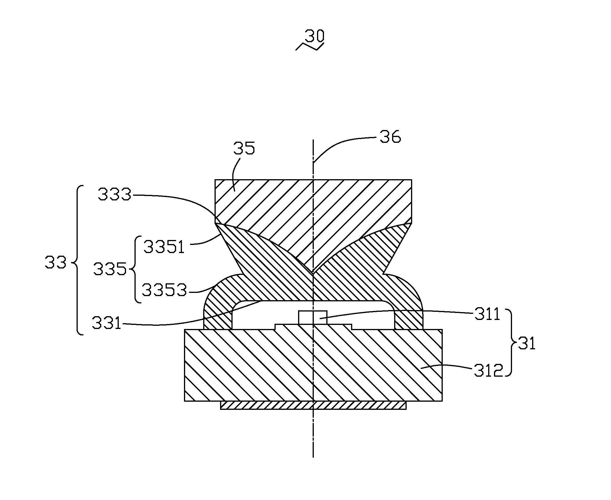
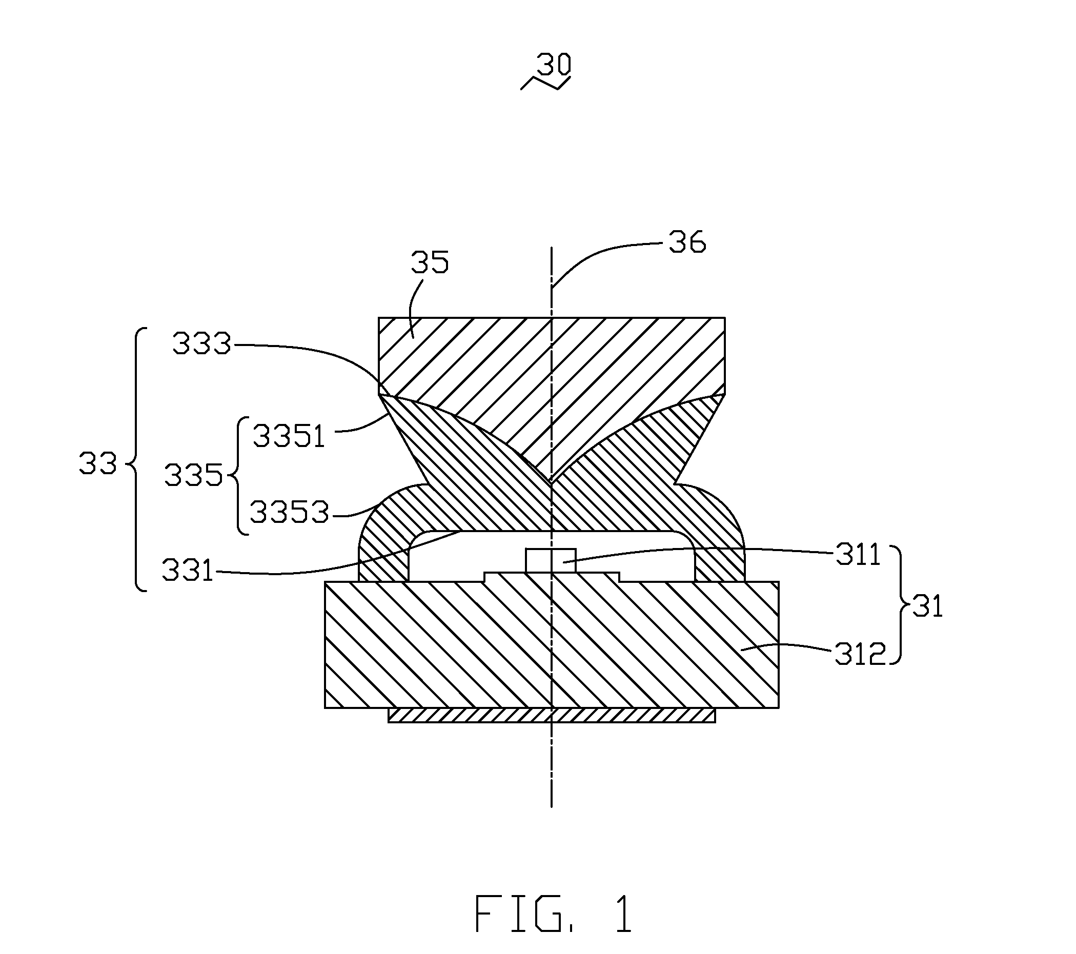
[0018]Referring to FIG. 1, a light emitting diode 30 in accordance with a first preferred embodiment is shown. The light emitting diode 30 includes a light output unit 31, an optical lens 33, and a reflective film 35. The light emitting diode 30 defines a central vertical axis 36 that passes through centers of the light output unit 31 and the optical lens 33. The light output unit 31 includes a base 312, and a semiconductor chip 311 fixed on the base 312. The semiconductor chip 311 has a light emitting PN (P-type silicon, N-type silicon) junction. The optical lens 33 includes a light input surface 331, a top interface 333 opposite to the light input surface 331, and a peripheral light output surface 335 generally between the light input surface 331 and the top interface 333. The light input surface 331 has an...


PUM


Abstract

An exemplary light emitting diode (30) includes a light output unit (31), an optical lens (33) and a reflective film (35). The optical lens includes a light input surface (331) facing the light output unit, a top interface (333) opposite to the light input surface, and a light output surface (335) between the light input surface and the top interface. The reflective film is integrally formed on and in immediate contact with the top interface of the optical lens. The reflective film is made of a transparent resin matrix material dispersed with a plurality of reflective particles. A method for making the light emitting diode is also provided.

Description

BACKGROUND OF THE INVENTION[0001]1. Field of the Invention[0002]The present invention relates to light emitting diodes; and more particularly to a side-emitting type light emitting diode typically employed by a direct type backlight module of a liquid crystal display, and method for making the light emitting diode.[0003]2. Discussion of the Related Art[0004]In a liquid crystal display device, liquid crystal is a substance that does not itself radiate light. Instead, the liquid crystal relies on light received from a light source in order to provide displaying of images and data. In the case of a typical liquid crystal display device, a backlight module powered by electricity supplies the needed light.[0005]Typically, a light source of a backlight module is one of the following two types: a cold cathode fluorescence lamp (CCFL), or a light emitting diode (LED). Disadvantages of a CCFL include high energy consumption, low optical uniformity, and poor purity of white light. In addition...

Claims


Application Information

Patent Timeline
Patent Type & Authority Patents(United States)
IPC IPC(8): H01L21/00H01L33/58H01L33/60
CPCH01L33/58H01L33/60Y10S362/80
Inventor CHANG, SHAO-HAN
Owner HON HAI PRECISION IND CO LTD
Why Eureka
Try Eureka