Pressure vessel with improved impact resistance and method of making the same

a pressure vessel and impact resistance technology, applied in the field of pressure vessels, can solve the problems of low impact damage tolerance of high-performance materials, inability to detect impact damage, and high cost, and achieve the effect of high degree of dispersibility

Active Publication Date: 2005-11-24
NASA
View PDF23 Cites 58 Cited by
  • Summary
  • Abstract
  • Description
  • Claims
  • Application Information

AI Technical Summary

Benefits of technology

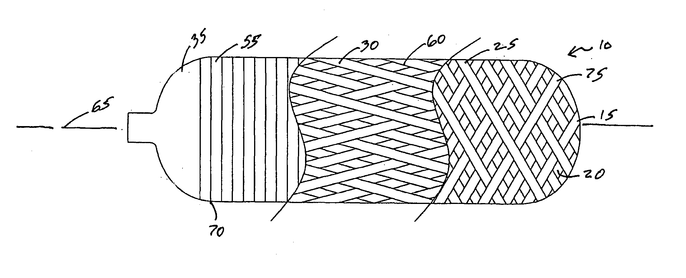
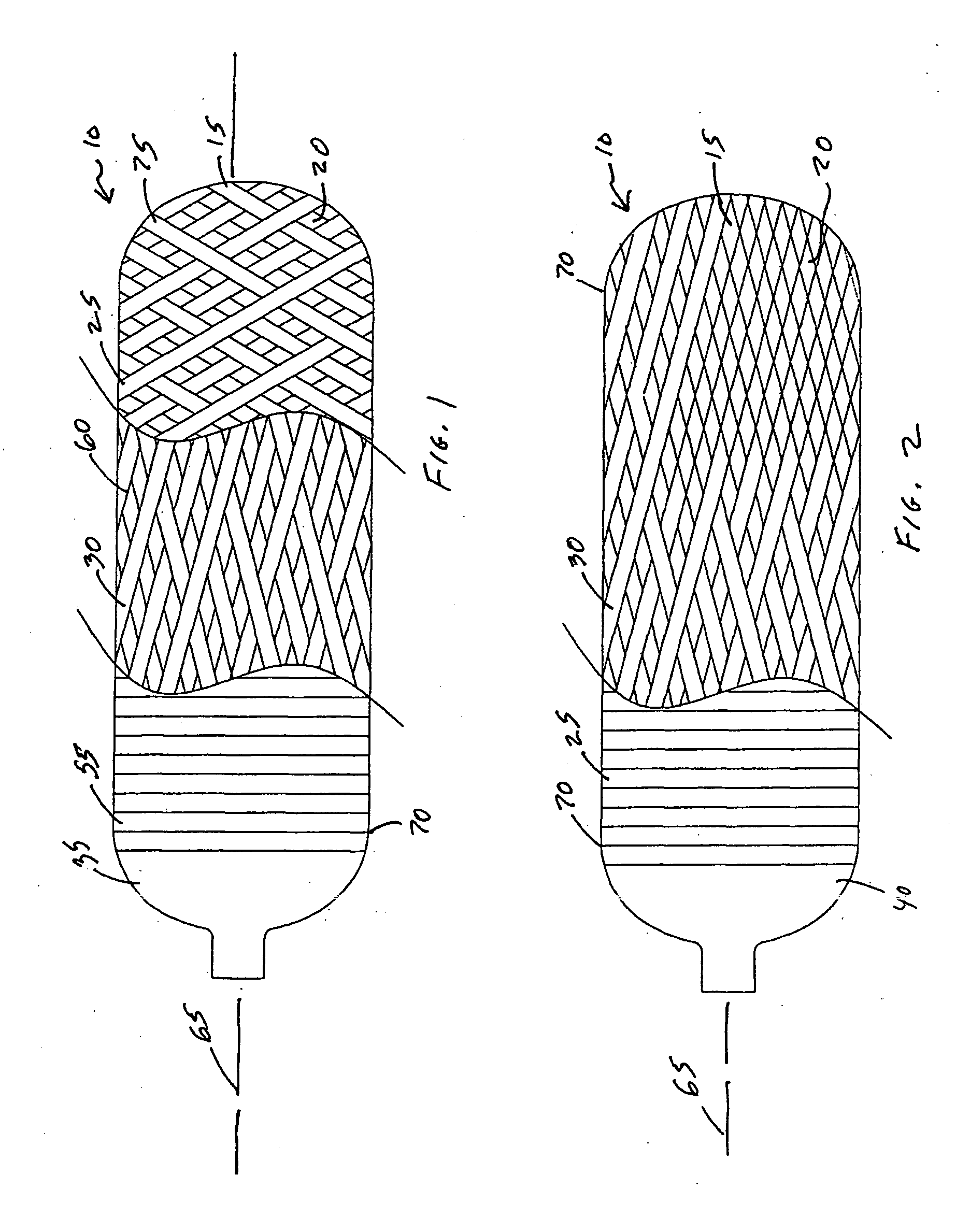
[0039] (33) In a further variant of the invention, a method of forming an improved pressure vessel includes the following steps. Providing a liner. Coating the liner with a primer. Drying the primer. Mounting the liner in a winding machine. Prepregnating at least first and second sets of fibers. Hoop winding the liner past the tangent points of the liner with either at least one layer of the first and second sets of fibers mixed together with a high degree of dispersement or at least one layer of fibers of either only the first set of fibers or only the second set of fibers. The hoop winding is at about 90° to a long axis of the liner. Helically winding the liner with either at least one layer of the first and second sets of fibers mixed together with a high degree of dispersement or at least one layer of fibers of either only the first set of fibers or only the second set of fibers. The helical winding is at about 5° to 20° to the long axis of the liner. Knuckle winding the liner with either at least one layer of the first and second sets of fibers mixed together with a high degree of dispersement or at least one layer of fibers of either only the first set of fibers or only the second set of fibers. The knuckle winding is at about 35° to 75° to the long axis of the liner. Repeating the hoop winding, helical winding and knuckle winding steps as required by vessel performance requirements. Applying shrink wrap material about an outer surface of the wound liner. Curing the pressure vessel in a curing oven.
[0040] (34) In still a further variant of the invention, a method of forming an improved pressure vessel 10 includes the following additional steps instead of prepregnating at least first 25 and second 30 sets of fibers. Mixing epoxy (not shown) and hardener (not shown) in required proportions in a resin bath apparatus (not shown). Directing at least one of first 25 and second 30 sets of fibers through the resin bath apparatus.
[0041] (35), (36) In yet a further variant, a method of forming an improved pressure vessel 10 includes the steps of forming the vessel 10 over a mandrel (not shown) rather than a liner 35. The liner 35 is removed after the vessel 10 is cured.
[0042] (37) In still another variant of the invention, the method of forming an improved pressure vessel includes the step of inserting at least one layer of fabric between layers of fiber winding. The fabric includes any of selected sets of fibers.
[0043] (38), (39) In final variants of the invention, the method of forming an improved pressure vessel includes applying at least one layer of fabric to the liner or mandrel with a resin material. The fabric includes any of selected sets of fibers

Problems solved by technology

However, a challenge presented by such new high performance materials is the low impact damage tolerance thereof.
Exploring the latter point in more detail, high performance, filament wound composite pressure vessels, such as are used in solid propellant propulsion, spacecraft energy storage systems, and other similar demanding applications, have always been susceptible to damage from low velocity impact in both operational and non-operational environments.
It is noted that these things may or may not degrade the capability of the pressure vessel and a particularly worrisome problem is that these impacts, and the damage therefrom, may not be detectable.

Method used


Image

  • Pressure vessel with improved impact resistance and method of making the same
  • Pressure vessel with improved impact resistance and method of making the same
  • Pressure vessel with improved impact resistance and method of making the same

Examples


Embodiment Construction

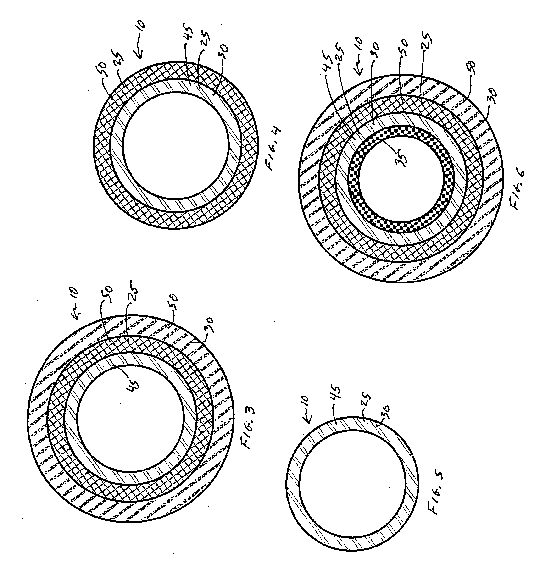
[0055] (1) An improved pressure vessel 10, as illustrated in FIGS. 1-7, 9 and 10, providing the desired features includes a composite material having fibers 15 located in a resin matrix 20. The improvement includes at least first 25 and second 30 sets of fibers 15.

[0056] (2) In a variant of the invention, the first set of fibers 25 includes high strength fibers.

[0057] (3) In a further variant, the first set of fibers 25 includes high modulus materials.

[0058] (4) In still a further variant, the second set of fibers 30 includes fibers having high toughness characteristics.

[0059] (5) In another variant, the second set of fibers 30 includes high modulus materials.

[0060] (6) In still another variant, the second set of fibers 30 includes fibers having low stiffness characteristics.

[0061] (7) In yet another variant, the second set of fibers 30 includes fibers having low compressibility characteristics.

[0062] (8) In still another variant of the invention, the first set of fibers 25 i...


PUM

PropertyMeasurementUnit
angleaaaaaaaaaa
angleaaaaaaaaaa
weightaaaaaaaaaa

Abstract

A composite overwrapped pressure vessel is provided which includes a composite overwrapping material including fibers disposed in a resin matrix. At least first and second kinds of fibers are used. These fibers typically have characteristics of high strength and high toughness to provide impact resistance with increased pressure handling capability and low weight. The fibers are applied to form a pressure vessel using wrapping or winding techniques with winding angles varied for specific performance characteristics. The fibers of different kinds are dispersed in a single layer of winding or wound in distinct separate layers. Layers of fabric comprised of such fibers are interspersed between windings for added strength or impact resistance. The weight percentages of the high toughness and high strength materials are varied to provide specified impact resistance characteristics. The resin matrix is formed with prepregnated fibers or through wet winding. The vessels are formed with or without liners.

Description

ORIGIN OF THE INVENTION [0001] This invention was made with Government support under contract NAS8-01146 awarded by the National Aeronautics and Space Administration. The Government has certain rights under this invention.FIELD OF THE INVENTION [0002] The present invention relates to pressure vessels and, more particularly, to a composite overwrapped pressure vessel having improved impact resistance. BACKGROUND OF THE INVENTION [0003] The development of advanced composite materials has enabled the development of tanks and pressure vessels which are of lightweight and which have very thin walls. It will be appreciated that for aerospace applications, weight is a key parameter. More specifically, weight conservation is extremely important in such aerospace applications because the lighter the tank or pressure vessel, the more weight that can be allotted to the vehicle payload. Stated differently, cost is a barrier for commercial space applications, and every pound saved in the weight ...

Claims


Application Information

Patent Timeline
Patent Type & Authority Applications(United States)
IPC IPC(8): B29C53/60B65D1/00B65D90/02B65H81/00
CPCB29C53/602B65D90/029Y10T428/1345Y10T428/1317Y10T428/1372Y10T428/1369
Inventor DELAY, THOMAS K.PATTERSON, JAMES E.OLSON, MICHAEL A.
Owner NASA
Why Eureka
Try Eureka