Communication transformer for power line communication

a technology of communication transformer and power line, which is applied in the direction of fixed transformer, inductance, and discontinuously variable inductance/transformer, etc., can solve the problems of low electrical balance of the transformer, noise radiated from the above-described transfer media, and common-mode noise, so as to achieve low common-mode rejection ratio, high common-mode rejection ratio, and low noise.

Inactive Publication Date: 2009-08-11
PANASONIC CORP
View PDF15 Cites 7 Cited by
  • Summary
  • Abstract
  • Description
  • Claims
  • Application Information

AI Technical Summary

Benefits of technology

[0008]In the communication transformer of the present invention, the additional winding provided between the transfer-purpose windings is employed as a shielded line, and also, the halfway portion of the additional winding is connected to the constant potential. As a result, there is such a merit that while the electrical balance of the transformer is not lowered, the high common-mode rejection ratio can be obtained. Also, since the impedance of the feedback path for the common-mode signal is lowered in the vicinity of the transfer signal frequency range, the larger amount of the common-mode signals can be fed back to the signal source side, so that there is an advantage that the high common-mode rejection ratio can be obtained.

Problems solved by technology

In connection with high transfer speeds, there is a problem that noise is radiated from the above-described transfer media.
In general, common-mode noise mainly constitutes noise radiation from balanced transfer paths such as twisted pair cables and parallel electric cables, while the common-mode noise is produced between the transfer paths and the ground.
However, in the conventional method, there is such a problem that since the additional winding 18 is grounded, the electrical balance of the transformer is lowered.
As a consequence, there is such a problem that the sufficiently high common-mode rejection performance cannot be essentially obtained.

Method used


Image

  • Communication transformer for power line communication
  • Communication transformer for power line communication
  • Communication transformer for power line communication

Examples


embodiment mode 1

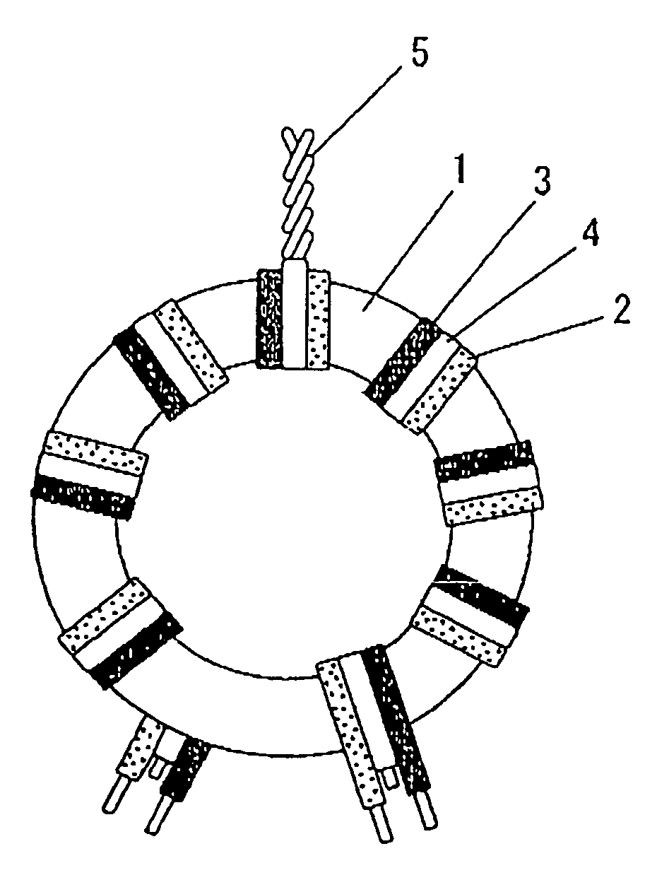
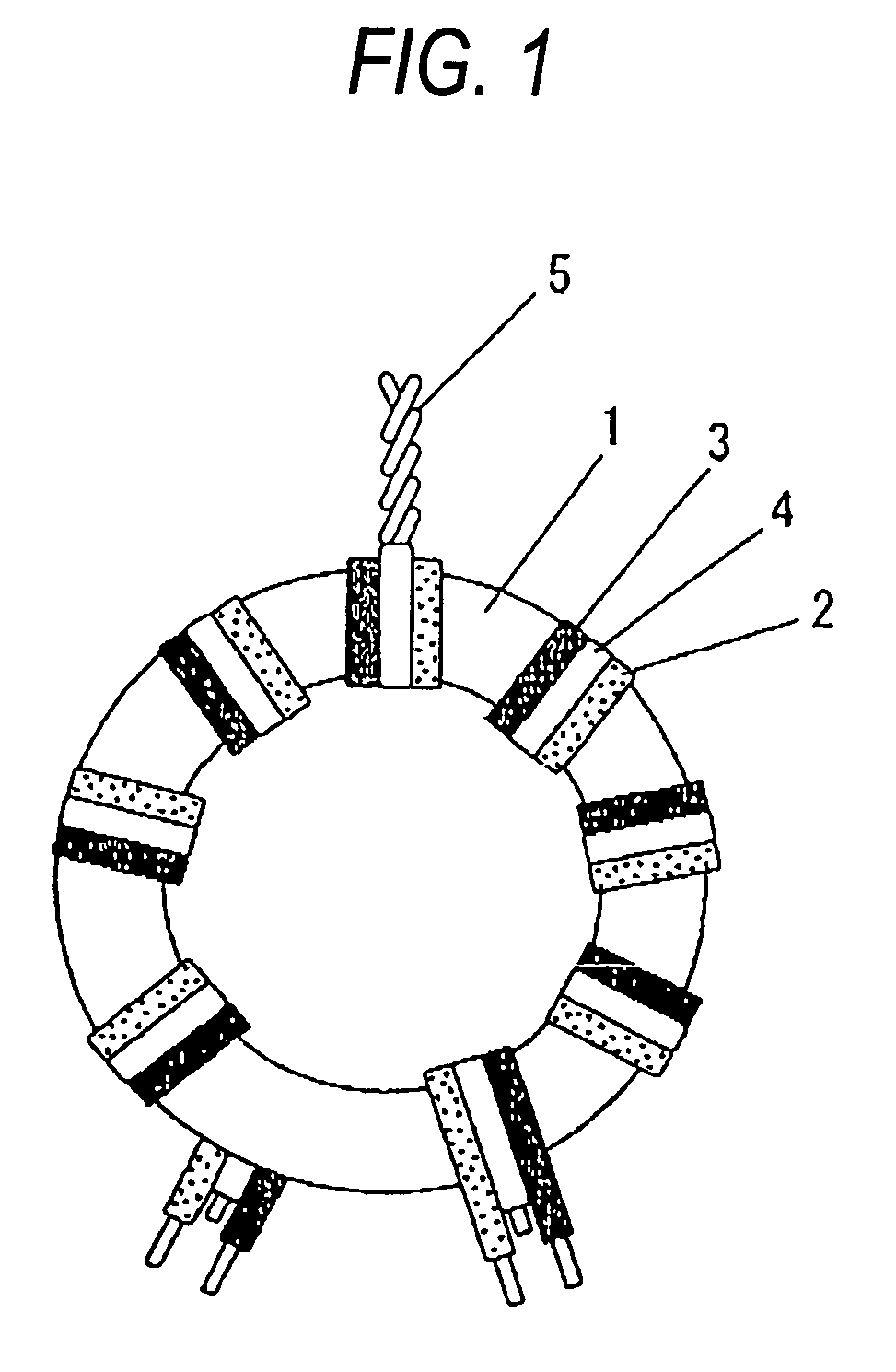
[0027]FIG. 1, FIG. 2, and FIG. 5 are front views of a communication transformer according to an embodiment mode 1 of the present invention. FIG. 3A and FIG. 3B are sectional views of windings in the embodiment mode 1 of the present invention. FIG. 4 and FIG. 6 are equivalent circuits of the communication transformers. Reference numeral 1 shows a magnetic core, reference numerals 2 and 3 represent transfer-purpose windings, reference numeral 4 indicates an additional winding, and reference numeral 5 represents a center tap. Although the magnetic core 1 is represented as a ring-shape form, the magnetic core 1 may be alternatively represented as an ellipse shape, or a horseshoe shape. Also, the magnetic core 1 may be suitably manufactured by using a magnetic material such as ferrite. The transfer-purpose windings 2 and 3, and also, the additional winding 4 are constituted by an electric wire such as a covered copper wire and a cable wire. The additional winding 4 corresponds to such a ...

embodiment mode 2

[0051]FIG. 7 is a front view of a communication transformer according to an embodiment 2 of the present invention. FIG. 8 is an equivalent circuit of the communication transformer shown in FIG. 7. Reference numeral 5c shows a capacitance element, and reference numerals 2 and 3 represent transfer-purpose windings. FIG. 7 indicates such a communication transformer that there are two pieces of transfer-purpose windings which are wound on a magnetic core 1, a center tap 5 constituting a half way portion of any one of these transfer-purpose windings is connected via the capacitance element 5c to a constant potential. Also, inductance elements 5a and 5b are connected to both terminals of the transfer-purpose winding 2c respectively. As compared with such a case that an additional winding, or the like, is not employed between the transfer-purpose windings 2c and 3c, an effect capable of reducing the stray capacitance produced between the transfer-purpose windings 2c and 3c is decreased. Ho...

embodiment mode 3

[0053]FIG. 9 is a front view of a communication transformer according to an embodiment mode 3 of the present invention. In the drawing, there is shown the communication transformer which is used in high-speed electric power line communications so as to transfer signals in a frequency range from 1 MHz to several tens MHz. The communication transformer shown in FIG. 9 is different from the communication transformer indicated in the embodiment mode 1, and employs such an arrangement that a shielded line is used as both one of transfer-purpose windings and an additional winding.

[0054]In this drawing, reference numeral 12 shows a shielded line, reference numeral 13 represents a center conductor, and reference numeral 14 denotes a shielding conductor. Both a transfer-purpose winding 2 and an additional winding 4 are formed in an integral body by employing the shielding conductor 14. The center conductor 13 of the shielded line 12 and the shielding conductor 14 correspond to the transfer-p...


PUM

PropertyMeasurementUnit
frequencyaaaaaaaaaa
frequencyaaaaaaaaaa
impedanceaaaaaaaaaa

Abstract

A communication transformer for power line communication includes a magnetic core, a plurality of transfer-purpose windings wound on the magnetic core, and an additional winding. The additional winding is wound on the magnetic core in such a manner that the additional winding is positioned between the plurality of transfer-purpose windings, and does not contribute in signal transfer operations. The communication transformer is arranged such that a half way portion of the additional winding along a length direction thereof is electrically connected to a constant potential.

Description

BACKGROUND OF THE INVENTION[0001]The present invention is related to a communication transformer employed in a LAN, or the like, in which a non-shielded twisted pair cable is used as a transmission path so as to perform a communicating operation. More specifically, the present invention is directed to a communication transformer which is employed in a power line communication, while the power line is used as a communication medium.[0002]Recently, non-shielded type twisted pair cables are mainly utilized as transfer media for LANs (Local Area Networks). In connection with high transfer speeds, there is a problem that noise is radiated from the above-described transfer media. More particularly, in electric power line communications in which electric power lines are employed as transfer media, since such media (namely, electric power line) which has not been originally designed as communication paths is used as these communication paths, noise suppressing solutions are strongly request...

Claims


Application Information

Patent Timeline
Patent Type & Authority Patents(United States)
IPC IPC(8): H01F27/28H01F19/08H01F19/00H01F21/12H01F27/00H01F27/36H01F27/38H01F27/42H01F30/00H01F30/16H03H7/09H04B5/00
CPCH01F19/08H01F27/38H01F30/16H04B5/0018H01F21/12H04B5/0093H04B5/0012H04B5/0087H03H2001/0092
Inventor YAMASHITA, AKIHIRO
Owner PANASONIC CORP
Why Eureka
Try Eureka