
Virtual data center for network resource management

a network resource management and virtual data center technology, applied in the field of data center systems, can solve problems such as server failure to function, license invalidation, and service disruption

Active Publication Date: 2009-08-11
DELL PROD LP
View PDF12 Cites 58 Cited by
  • Summary
  • Abstract
  • Description
  • Claims
  • Application Information

AI Technical Summary

Benefits of technology

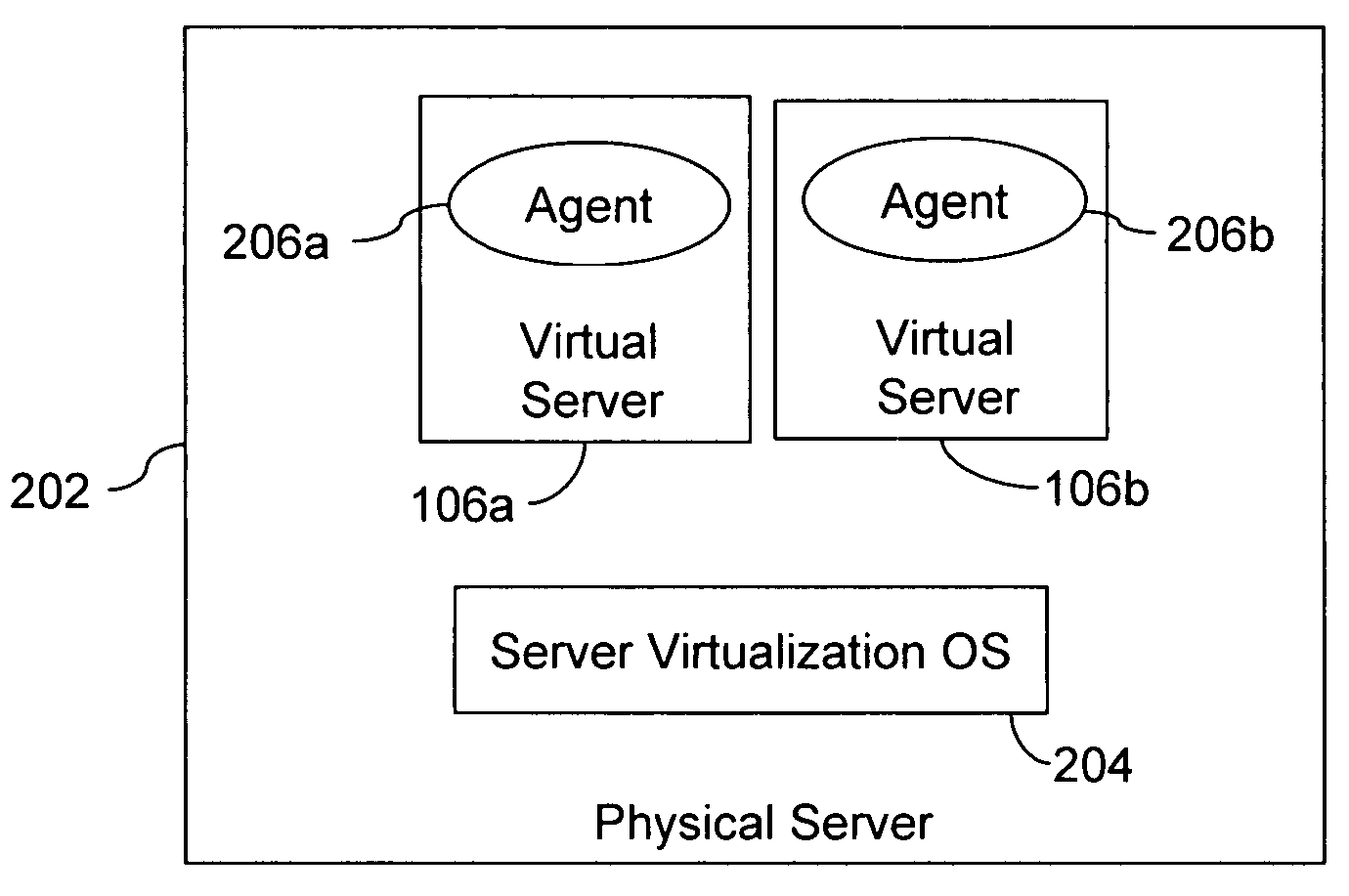
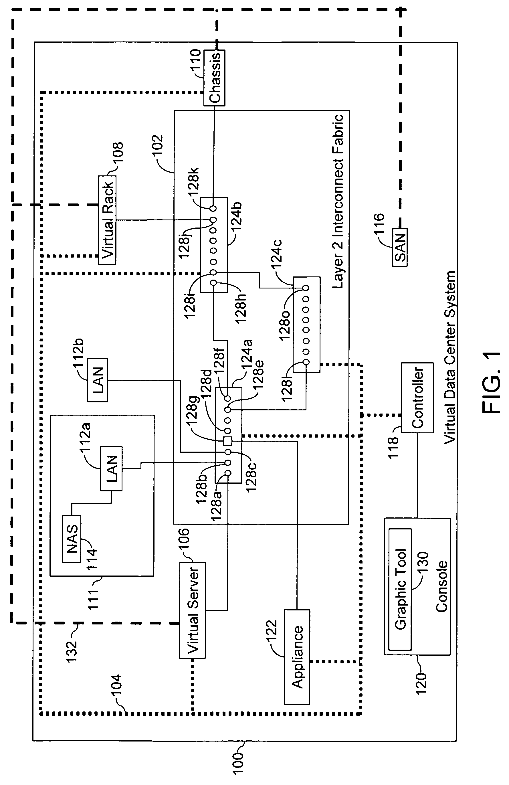
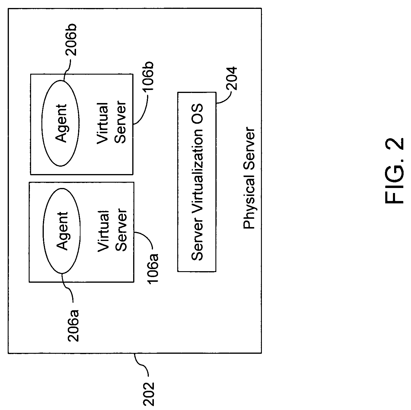
[0013]A VDC system includes a network of servers, a layer 2 interconnect fabric, a controller, an agent, and a system management infrastructure. Each server in the network of servers requires a server image to boot. The required server image may be stored on a local disk on the server or on a remote storage device. The layer 2 interconnect fabric includes ports, which provide connectivity to the network of servers. The controller configures and assigns server images to the servers dynamically. The agent resides on each of the plurality of servers and enables communication between the controller and the VDC system.

Problems solved by technology

As a result, the license may be invalidated, and the server unable to function until the network administrator manually provides a new MAC address.
This often results in disruption of service.
However, if the server function moves to another server with its own HBA, or if the HBA on the server is changed, then the server may lose access to information on the SAN.
If the server hardware is replaced, or if the NIC or the HBA is changed, the server cannot boot without appropriate configuration changes made by the data center administrator.
The process of reconfiguration is prone to errors and may result in interruption to the service, and permanent loss of critical data.
However, these methods do not address the problems associated with LAN and SAN identity changes, caused by changes in the server hardware.
This results in an exponential increase in the number of server resources, as well as in the management, and the operational cost and complexity.

Method used


Image

  • Virtual data center for network resource management
  • Virtual data center for network resource management
  • Virtual data center for network resource management

Examples


example 1

[0046]

(1)preferred=“largeMemory” / >(2)(3)

[0047]In example 1, command line (1) states that the unique server image identifier is ‘5’ and the server image requires a net boot. Command line (2) states the hardware attributes associated with the server image, i.e., it requires at least a medium memory and prefers a large memory. Command line (3) states the network connectivity-related attributes, i.e., the path where the image has been stored.

example 2

[0048]

(1)(2)(3)

[0049]In example 2, command line (1) states that the unique server image identifier is ‘6’, and the server image requires a SAN boot. Command line (2) states the hardware attributes associated with the server image, i.e., it has no memory specifications and will work with any available memory size. Command line (3) states the network connectivity-related attributes, i.e., the WWN of the SAN, where the image is stored.

[0050]Proxy agent 504 enables controller 118 to establish a communication link with external appliances such as appliance 122, interconnect switches such as switches 124, and remote management NICs on stand-alone or virtual rack servers such as remote management NIC 306 on stand-alone server 302. Controller 118 configures appliance 122, using proxy agent 504. Proxy agent 504 configures the load balancer to incorporate the required persona into the load-balancing pool of the load balancer. Proxy agent 504 also enables appliance 122 to appear in the topolog...


PUM


Abstract

A system and a method for implementing a virtual data center. In which, the functions to be performed by a computer, and the access the computer equipment is required to have to the storage and network facilities, are decoupled from the hardware, and instantiated dynamically on any suitable computer equipment, without any manual intervention. In a virtual data center, all the physical resources are virtualized and arranged dynamically, to meet the functional requirements of the data center.

Description

BACKGROUND[0001]The present invention relates to the field of Data Center Systems (DCS). More specifically, it relates to a system and method for implementing a Virtual Data Center (VDC) system in a network of physical devices.[0002]A computer network includes a plurality of network devices such as servers, firewalls, and other such appliances. Servers may be categorized as physical servers and virtual servers. Examples of physical servers include stand-alone and blade servers. Examples of virtual servers include servers created by systems that divide a physical server into one or more parts, each of which can host an independent operating environment. A server has a Network Interface Card (NIC) that connects the server to one or more Local Area Networks (LANs). The NIC has a unique Medium Access Control (MAC) address. The MAC address serves as an identifier of the server on a LAN. The present state of the art provides communications protocols, which use dynamic methods, e.g., Addre...

Claims


Application Information

Patent Timeline
IPC IPC(8): G06F15/177G06F15/16G06F9/445
CPCH04L41/0869H04L41/0806H04L41/046H04L41/12H04L41/40
Inventor STEIN, LAWRENCEBIGALL, EVANGREER, RUSSELL SJASZEWSKI, GARYOBERHAUS, JARED
Owner DELL PROD LP
Learn More