Resilient clip-on member for dust mop or other work member

a clip-on member and dust mop technology, which is applied in the direction of wing knobs, rod connections, carpet cleaners, etc., can solve the problems of dusty dust, dusty and/or wet, and difficult installation/removal of the connection head, etc., to facilitate hands-free engagement.

Active Publication Date: 2009-08-18
CHIEF MFG
View PDF28 Cites 31 Cited by
  • Summary
  • Abstract
  • Description
  • Claims
  • Application Information

AI Technical Summary

Benefits of technology

[0010]The outer engagement slot is adjacent an opening between the upper edges of the jaws to facilitate hands-free engagement of the resilient member on the wire of the mop head. The inner portion of the engagement slot is substantially closed due to the compression from the integrally-formed spring, with the integral spring being defined by the respective second inner groove on each jaw of the pair of jaws.

Problems solved by technology

Dust mops, wet mops and push brooms have a problem in that it is desirable to change the mop head (or broom head) from time to time, but connections are typically either difficult to install / remove the head, or do not keep the head properly attached to the handle.
Often the old mop head is dirty, dusty and / or wet, and it is not desirable to have to handle the mop head, or have it very close the user performing the removal / replacement.
This type of connection is complex and subject to wear and tear.
Additionally, the spring and pivot rod, which are typically constructed of metal, are prone to rust out, particularly after repeated exposure to water and / or damp areas.
Thus, this type of device does not provide a true hands free operation, and in the case where the lever strikes an object that is stationary, such as a chair or table leg, the compressive force against the lever will open the clamp and cause the attachment to slip off the wire, thus unintentionally disconnecting the mop head from the wire.

Method used


Image

  • Resilient clip-on member for dust mop or other work member
  • Resilient clip-on member for dust mop or other work member
  • Resilient clip-on member for dust mop or other work member

Examples


Embodiment Construction

[0025]The invention will be illustrated in an embodiment typically connecting a dust mop handle to a pivot bar of a wire frame of a dust mop head. However, as indicated above, the present connecting device may connect a handle to other heads of other cleaning devices having a pivot bar, for example, wet mops and push brooms.

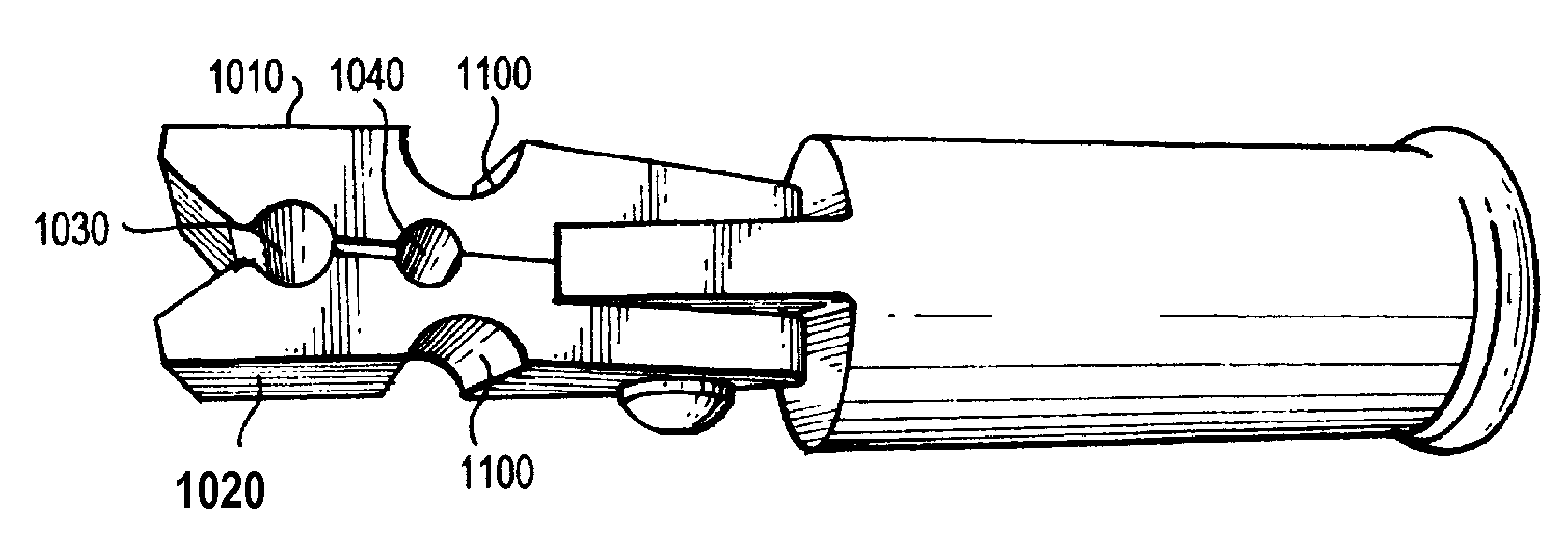
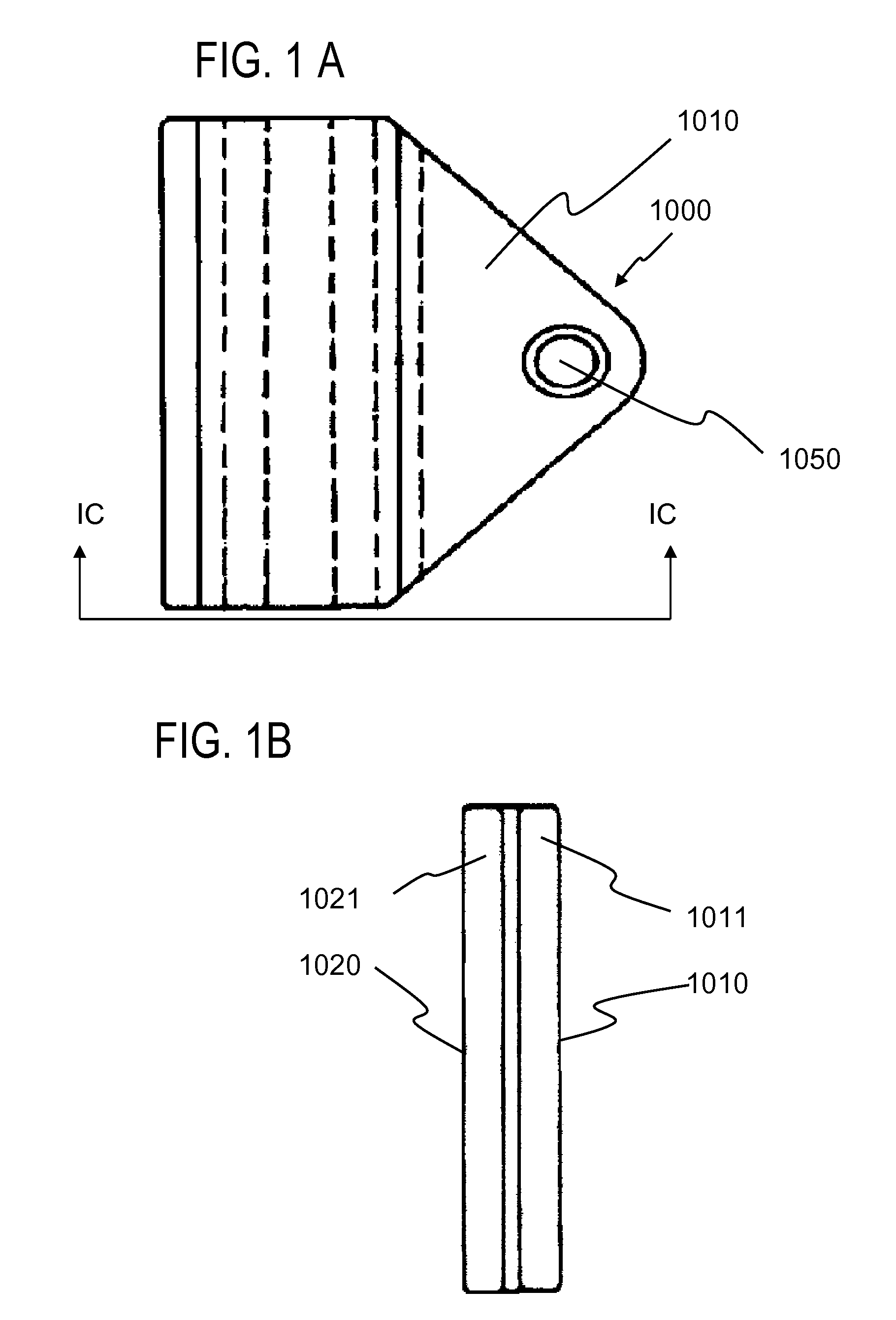
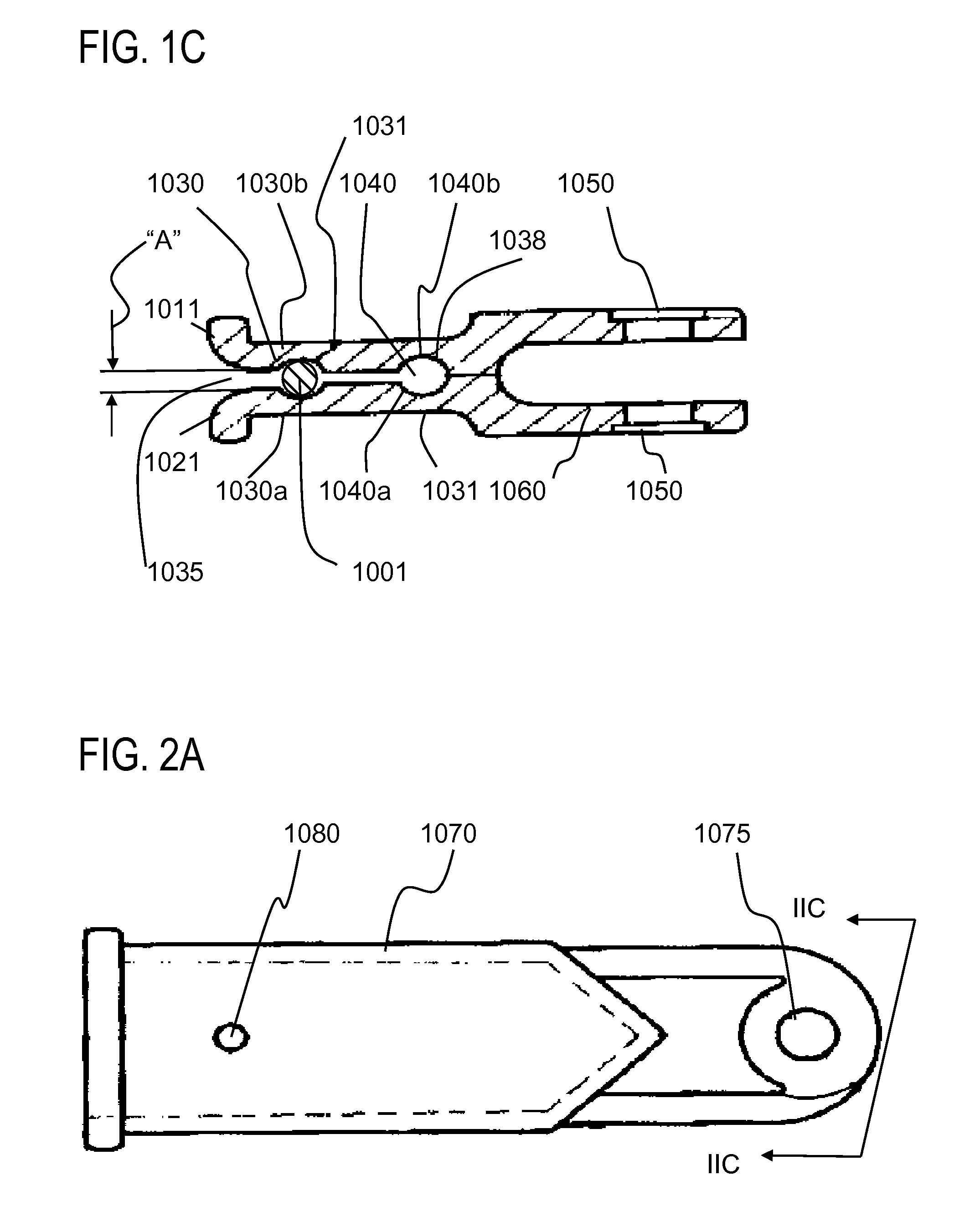
[0026]Referring to FIGS. 1A, 1B and 1C, the resilient clip-on member 1000 is preferably constructed of a single elastomeric and / or plastic material. A single piece may be molded of one piece or be made by molding two halves and permanently attaching or welding together the two halves as shown in FIG. 1C.

[0027]The resilient clip-on member 1000 has first and second jaws 1010 and 1020, respectively. Each of the jaws 1010, 1020 has a respective edge 1011, 1021, which are flared (as shown in FIG. 1C), but they could also be beveled (as shown in the photo in FIG. 3A). The jaws being made of resilient or elastomeric material, such as a resilient polymer and defining an ...


PUM


Abstract

A resilient device for joining a handle to a pivot bar of a wire support frame of a dust mop or other work member which allows for hands free operation to attach and remove the mop head or other work member. The holder includes a resilient member having first and second jaws extending generally parallel from one end of a base. Each of the jaws has an inner wall and an outer wall and which define at least an outer engagement slot and an inner engagement slot between their respective inner walls. The jaws also define an open end distal to the base and a closed end proximal or at the base. The outer engagement slot being arranged transversely to an axial direction of the first and second jaws proximal to an open end portion of the jaws opposite to the base. The inner slot is proximal to a closed end portion of the jaws proximal to the base. Typically, the entire apparatus can include a single or unitary piece of plastic or a single substance.

Description

FIELD OF THE INVENTION[0001]The invention is related to connectors for cleaning devices, such as a work member selected from the group consisting of a dust mop, a wet mop, and a push broom. For example, the invention is related to devices that connect a mop handle to a dust mop head.BACKGROUND OF THE INVENTION[0002]Dust mops, wet mops and push brooms have a problem in that it is desirable to change the mop head (or broom head) from time to time, but connections are typically either difficult to install / remove the head, or do not keep the head properly attached to the handle. For example, some mop heads utilize a series of wing nuts that are connected to a connecting portion of a handle, which often requires the user to have to handle the mop head in close visual range to attach or remove the head from the handle. Often the old mop head is dirty, dusty and / or wet, and it is not desirable to have to handle the mop head, or have it very close the user performing the removal / replacement...

Claims


Application Information

Patent Timeline
Patent Type & Authority Patents(United States)
IPC IPC(8): B25G1/10
CPCB25G3/38Y10T403/53
Inventor FULLER, DANIEL T.ROBERSON, ROBERT LEE
Owner CHIEF MFG
Why Eureka
Try Eureka