Trace chemical sensing

a technology of trace chemical and detection field, which is applied in the field of trace chemical traces of substances, can solve the problems that the high pressure tank of gas may not be acceptable in a public area, and achieve the effect of increasing the sampled area of the target surface and reducing the time required

Inactive Publication Date: 2009-08-18
LEIDOS SECURITY DETECTION & AUTOMATION INC
View PDF16 Cites 18 Cited by
  • Summary
  • Abstract
  • Description
  • Claims
  • Application Information

AI Technical Summary

Benefits of technology

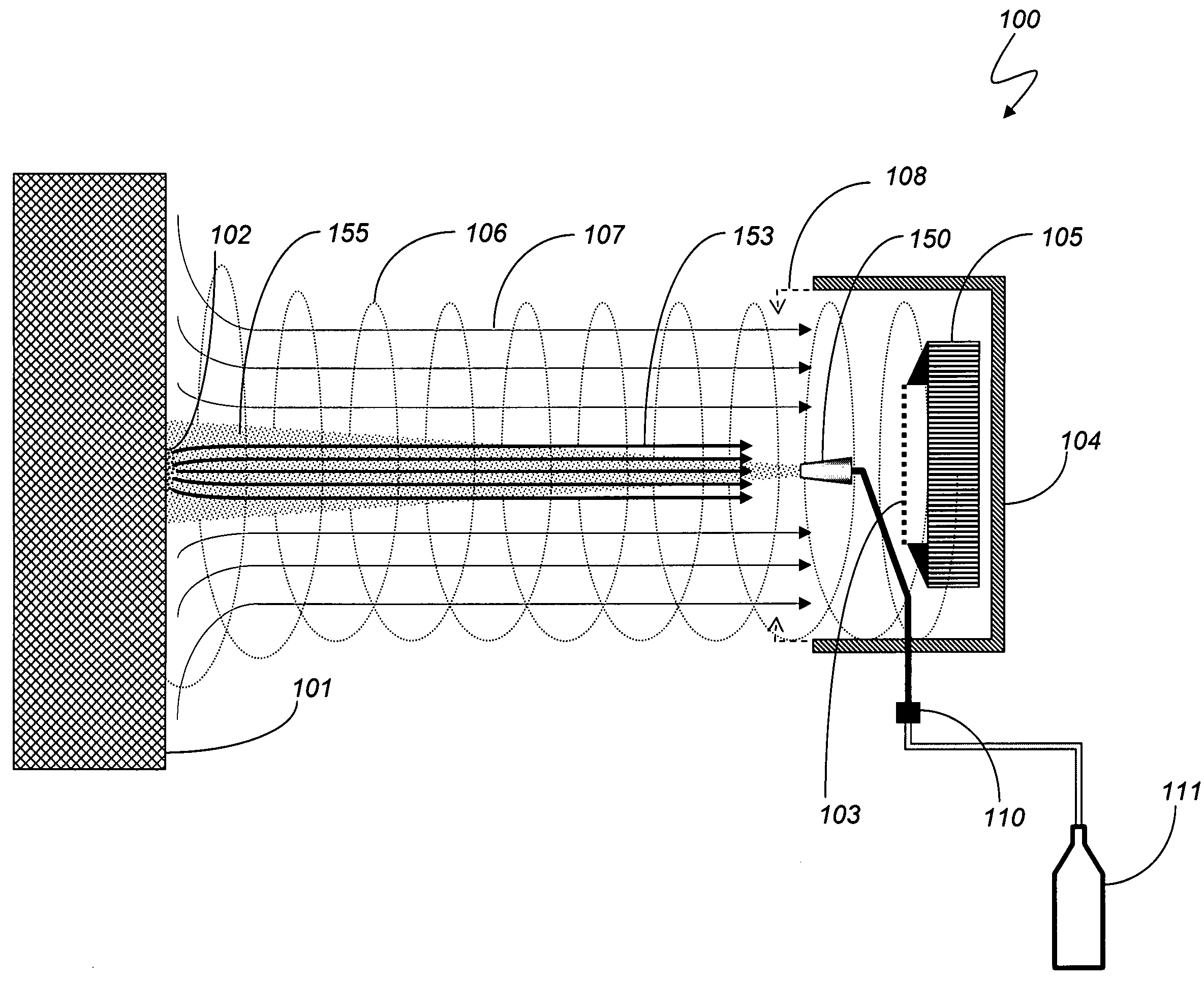
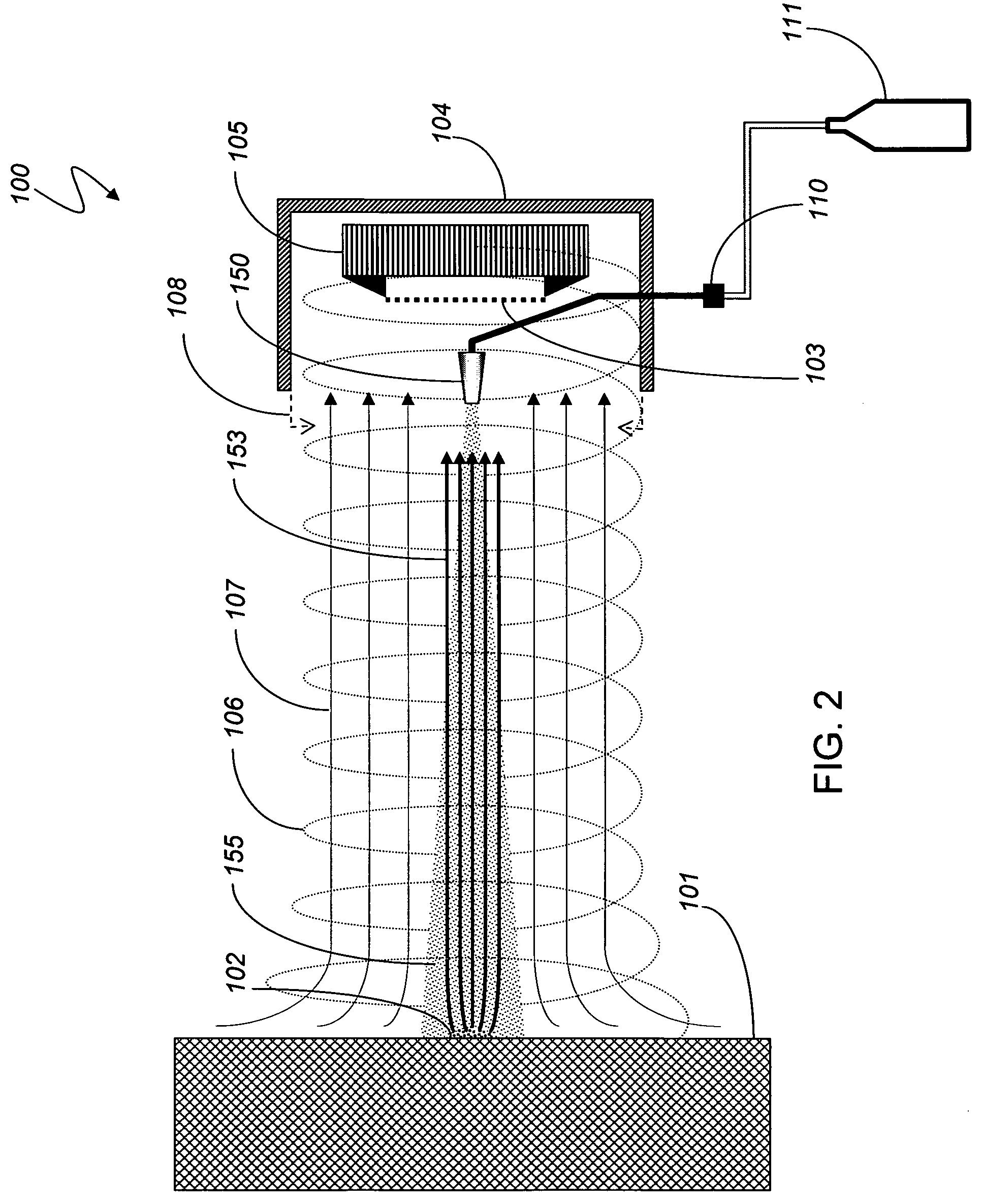
[0013]According further to the system described herein, a trace sample collection system is provided for the purpose of collecting a target particle sample while the target surface and the trace sample collection system are in relative motion. Relative motion is defined as a relative velocity across the line-of-sight between the target surface and the trace sample collection system, and may be greater than fifteen centimeters (six inches) per second. For example, objects moving on a belt often may be moving at a speed greater than fifteen centimeters (six inches) per second, and speeds up to sixty centimeters (two feet) per second are common. A walking person may be moving at a speed between sixty and one hundred centimeters (two to three feet) per second. Moving vehicles can be much faster.
[0020]According further to the system described herein, the gas of the blowing and spinning gas stream may be at least one of air, nitrogen, carbon dioxide, or argon. The gas of the blowing and spinning gas stream may be heated above ambient temperature. Further, the gas of the blowing and spinning gas stream may contain additive chemicals to enhance the detection performance of the sample collection system.
[0024]According further to the system described herein, a plurality of trace sample collection systems may be employed in order to increase the sampled area of target surface as well as decrease the time required to obtain said sample. An example of the use of a plurality of trace sample collection systems would be at least one vertical array of trace sample collection systems disposed to one or both sides of a walking person, said arrangement referred to as a turnstile. Another example would be at least two sample collecting systems disposed at the sides of a moving belt carrying packages or baggage. At least one other trace sample collection system could be optionally disposed over the moving belt. Additionally, additional trace sample collecting systems may be optionally added for the purposed of permitting an increase of the belt speed by alternating which of the trace sample collecting systems is currently sampling and which is currently analyzing a sample previously collected.

Problems solved by technology

The pressure of the pressurized gas may be about one hundred pounds per square inch, a value easily obtained with small compressors, but significantly higher pressures may also be employed, and may be limited only by the availability, cost, and safety restrictions for the pressurized gas.
For example, a high pressure tank of gas may not be acceptable in a public area due to the risk of explosion caused by mishandling.

Method used


Image

  • Trace chemical sensing
  • Trace chemical sensing
  • Trace chemical sensing

Examples


Embodiment Construction

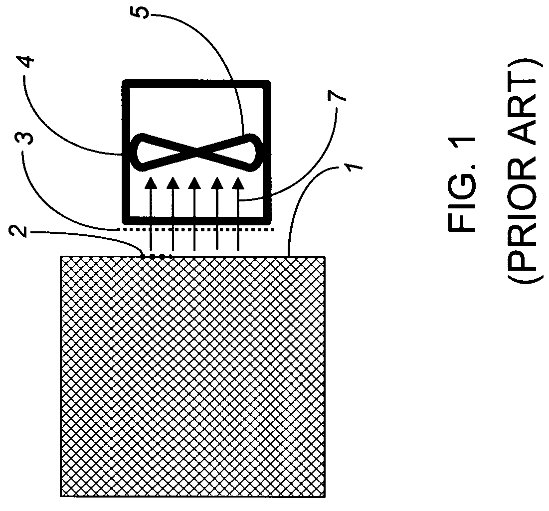
[0033]A handheld vacuum with a trace particle collection filter used in conjunction with existing wiping systems is illustrated in FIG. 1 showing basic features of non-contact particle collection system based on the existing state-of-the-art. The sample collection device 4 is brought in very close proximity to a target surface 1 that may have a trace sample of target particles 2. The vacuum pump 5 of the sample collection device 4 is activated, creating an inward flow of air 7. Sample collecting media 3 is disposed between the target surface 1 and the vacuum pump 5 such that any trace particles may be collected on or in the sample collecting media 3. The sample collecting media 3 may be a filter, such as chemical filter paper. The sample collecting media 3 is then removed from the sample collection device 4 and transported to a separate detection instrument in order to determine if trace particles of the target substance were collected. The separation distance between the sample col...


PUM

PropertyMeasurementUnit
relative velocityaaaaaaaaaa
diameteraaaaaaaaaa
relative velocityaaaaaaaaaa

Abstract

An explosive and narcotics detection system detects the presence of trace particles of materials that are adhering to surfaces. In order to detect such particles, to the particles are first dislodged or released from the surface, then transported to the detection instrument, and then accumulated on or in a particle collection device. When the sample collecting system and the target surface are in relative motion across the line-of-sight greater than fifteen centimeters per second, non-contact sample collection may be accomplished using a vortex or vortex attractor particle collector together with a plurality of air or aerosol jets. A plurality of large diameter vortex collectors may obtain samples at relative line-of-sight velocities greater than five feet per second over a large surface area and for a complex-shaped surface.

Description

CROSS-REFERENCE TO RELATED APPLICATIONS[0001]This application is a Continuation-in-part of U.S. application Ser. No. 11 / 492,672, filed Jul. 25, 2006 (pending), which is a Continuation-in-part of U.S. Ser. No. 11 / 258,477, filed Oct. 25, 2005 (pending), and which claims priority to Provisional Application 60 / 708,017, filed Aug. 12, 2005 (expired), and which is a Continuation-in-part of U.S. Ser. No. 10 / 890,820, filed Jul. 14, 2004 (now U.S. Pat. No. 7,098,672), which is a Continuation-in-part of U.S. Ser. No. 10 / 349,491, filed Jan. 22, 2003 (now U.S. Pat. No. 6,828,795), which is a Continuation-in-part of U.S. Ser. No. 10 / 295,039, filed Nov. 14, 2002 (abandoned), and which is a Continuation-in-part of U.S. Ser. No. 10 / 295,010, filed Nov. 14, 2002 (now U.S. Pat. No. 6,861,646), which claims priority from Provisional Application 60 / 363,485, filed Mar. 12, 2002 (expired), and Provisional Application 60 / 357,618, filed Feb. 15, 2002 (expired), and Provisional Application 60 / 357,394, filed ...

Claims


Application Information

Patent Timeline
Patent Type & Authority Patents(United States)
IPC IPC(8): G01N1/02G01N1/08G01N1/22G01N1/40
CPCG01N1/02G01N1/2273G01N33/48714G01N2001/028G01N2001/022
Inventor BUNKER, STEPHEN N.
Owner LEIDOS SECURITY DETECTION & AUTOMATION INC
Why Eureka
Try Eureka