Controllable watch winder for self-winding watches

a watch winder and watch technology, applied in the direction of electric winding, instruments, horology, etc., can solve the problems of rotor oscillation back and forth, inability to fully rewind, and inability to self-winding watches, so as to save power, facilitate watch inserting, and facilitate use and adaptability.

Active Publication Date: 2009-08-18
WOLF 1834 +1
View PDF25 Cites 37 Cited by
  • Summary
  • Abstract
  • Description
  • Claims
  • Application Information

AI Technical Summary

Benefits of technology

[0009]Briefly, and in general terms, the present invention provides an improved watch winder. In particular, the present invention provides a method and apparatus for winding a watch in such a manner that will save power, at the same time as providing greater assurance that the watch will be fully wound at the completion of the winding process when the user decides to wear the watch. The invention provides for greater ease of use and adaptability in a watch winder in that the invention caters to various types of self-winding watches with differing winding mechanisms. It also allows the user to more easily insert the watch on the winder.
[0010]More specifically, and in a presently preferred embodiment, by way of example, and not necessarily by limitation, the watch winder of the present invention includes a rotatable turntable adapted to rotate a self winding watch, a motor configured to rotate the turntable, and an electronic circuit to control the motor, the circuit being configured to commence rotation of the turntable after first introducing a period of delay after the circuit is activated. Such delay facilitates ease of use by the user, and efficiency of battery energy consumption.
[0013]Another aspect of the present invention is directed to a cuff configured to allow a wrist watch to be easily mounted upon it, for insertion into the turntable of the watch winder. The cuff includes an inner core of open cell foam and a covering of porous material, both core and material being chosen for their characteristic of high porosity, allowing the rapid ingress and escape of air when the cuff is compressed, and when compressive force is released. This quality allows the cuff to be rapidly compressed to facilitate mounting and demounting of a wrist watch.

Problems solved by technology

When the watch is worn, the random movements of the wearer cause the rotor to oscillate back and forth, or to spin completely about its axis, to wind the mainspring.
Once the spring is unwound, a self-winding watch cannot, as can a manually wound watch, be fully rewound in a few seconds by the user.
The task of maintaining multiple watches wound and operating is an inconvenience, and may also include resetting the time on the watch each time the spring runs down.
Yet, a number of problems are encountered in the prior art.
This may be unproblematic for most self-winding watches, but where the watch is large or heavy, the weight of the watch may cause the powered winding mechanism to slow down, resulting in the watch being not completely wound after the spindle ceases turning.
These factors introduce problems for watch winding mechanisms configured to run for a set period of time.
A further problem may be encountered with prior art watch winders if, for example, a user places his watch in a winder and starts it running intending to leave the watch in the winder for, say, 36 hours before he wears it.
This is an inefficient use of battery energy, and may even be mechanically undesirable for the watch.
Alternatively, under the same circumstances, if the user places his watch in a winder knowing it is fully wound, then 36 hours may be spent winding a fully wound watch, to even greater wasteful effect.
The prior art has not sufficiently taken into account such questions of battery efficiency.
Further, the prior art has not adequately provided for various aspects of convenient use, such as where different watch types have mechanisms with different winding requirements.
Problems can be encountered in that certain self-winding watches may have a plurality of spring mechanisms, or so-called “complications,” dedicated to running separate features of the watch.
However, some self-winding watches are only wound by the rotor rotating in one direction, either clockwise, or anticlockwise, so that alternating the direction of rotation may actually amount to a waste of battery energy in the case of such watches.
This pattern of intermittent operation with frequent starts and stops, while adequate to wind many self winding watches, has the disadvantage of resulting in an inefficient use of stored battery power.

Method used


Image

  • Controllable watch winder for self-winding watches
  • Controllable watch winder for self-winding watches
  • Controllable watch winder for self-winding watches

Examples


Embodiment Construction

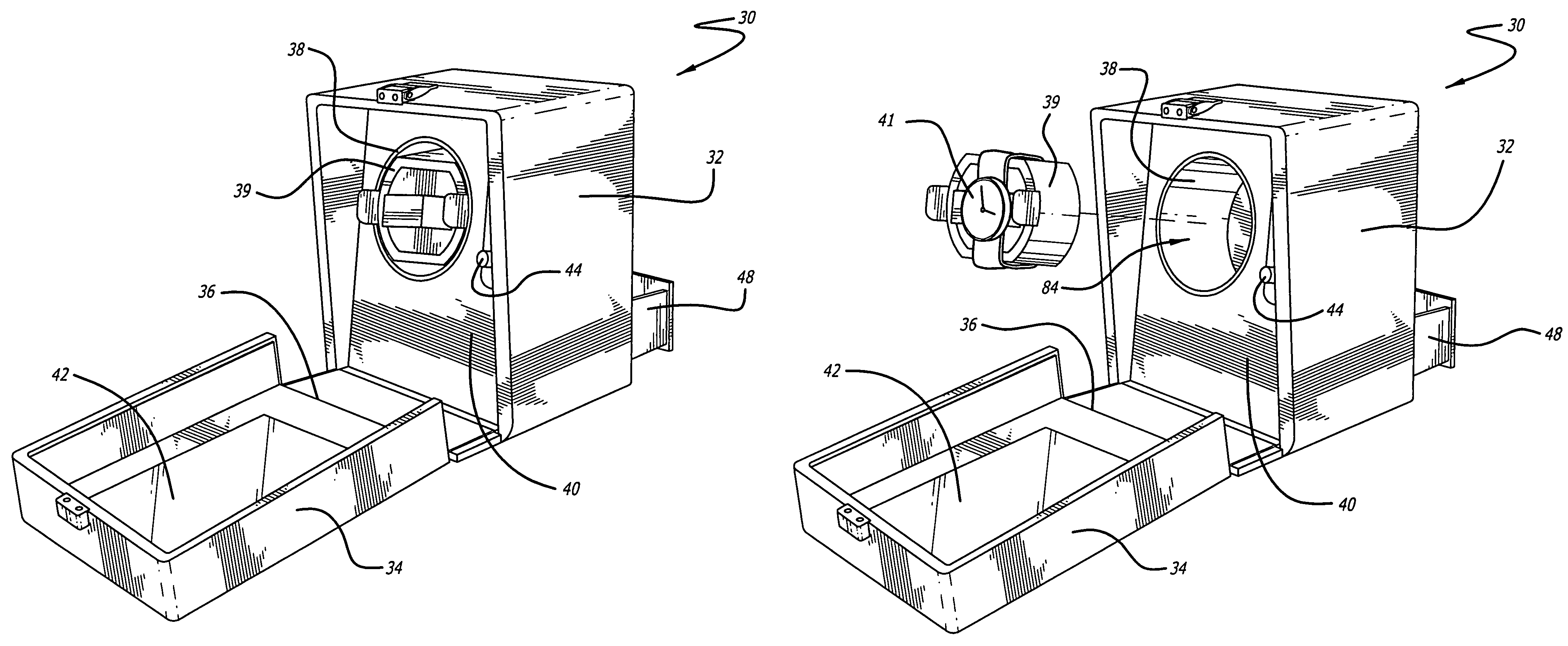
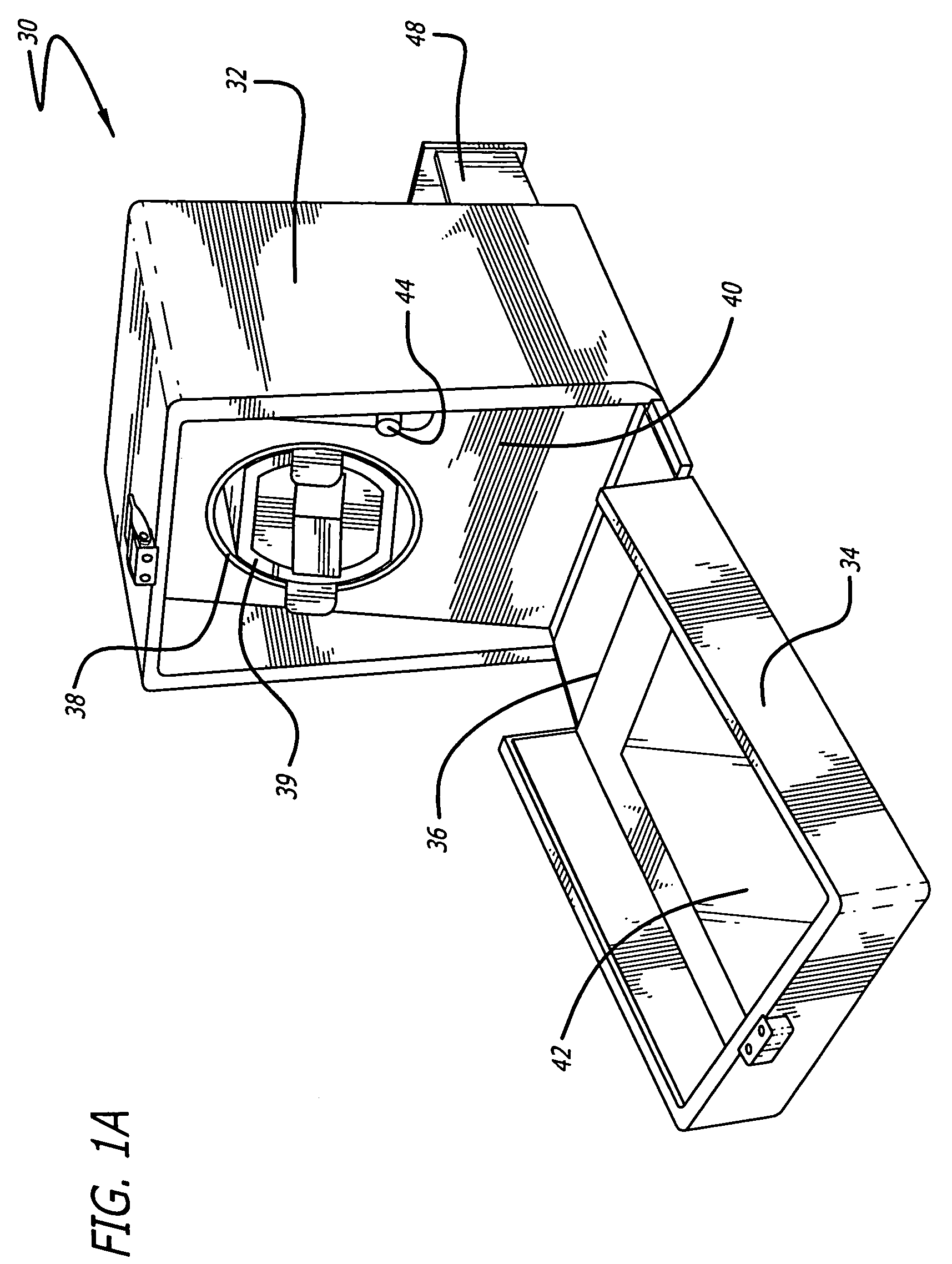
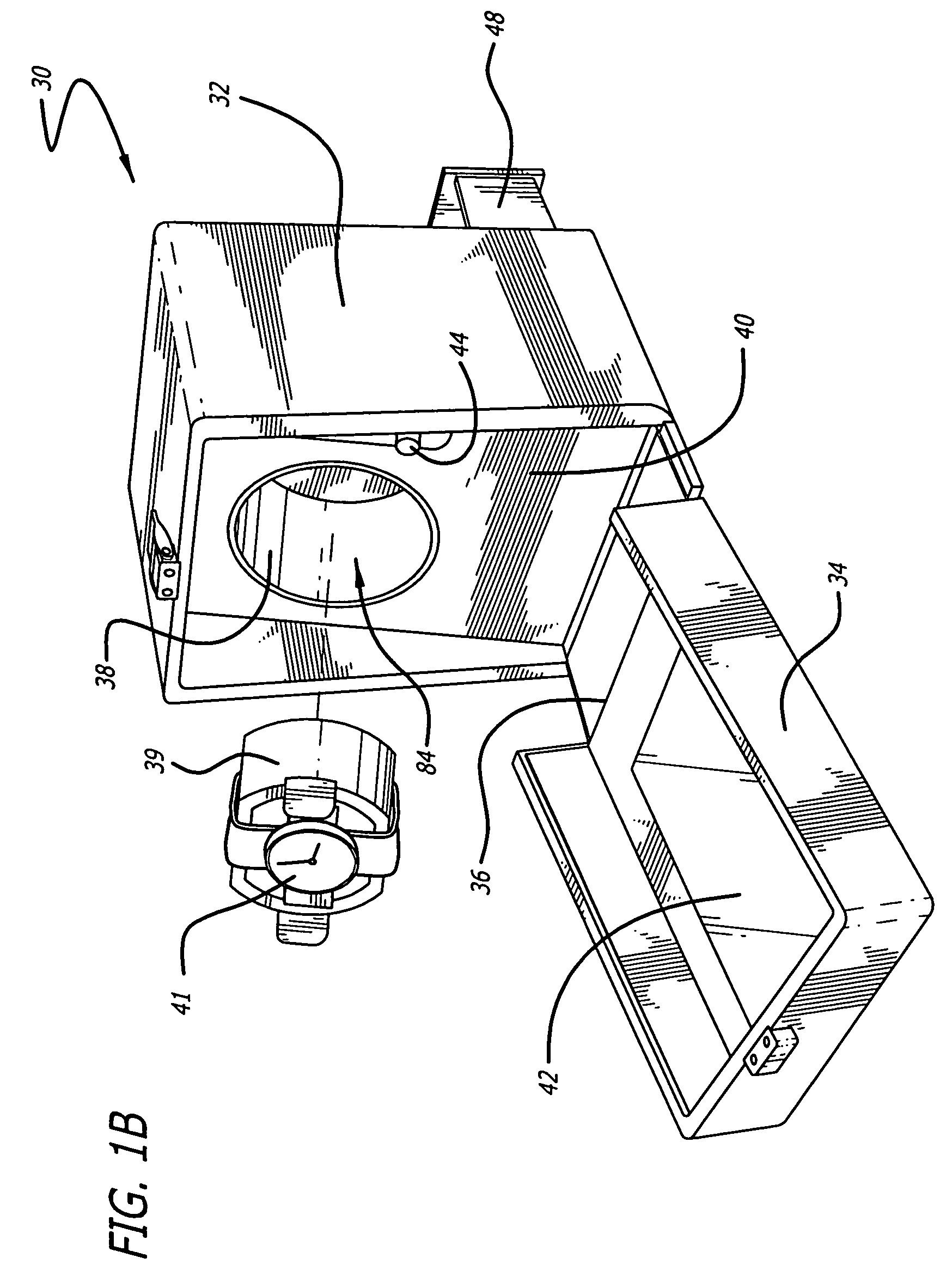
[0039]With reference to the drawings, which are provided for purposes of exemplary illustration, a new and improved watch winding mechanism and method embodying the principles and concepts of the present invention and generally designated by the reference number 30 will be described.

[0040]In a preferred embodiment as shown in FIGS. 1A and 1B, a watch winder 30 has a rectangular sided exterior housing 32 including an exterior front cover 34 that opens downwardly about a bottom hinge 36 to expose a turntable 38 mounted centrally on an interior front wall 40. A cylindrical cuff 39 is provided, configured to be removable from the turntable to permit a watch 41 to be mounted on the cuff, so that the cuff and watch combination may be installed on the turntable 38. The front cover 34 may include a glass or plastic transparent window 42 for viewing the contents of the housing. Also mounted on the interior front wall 40 are control switches 44, 46 (46 not visible in FIGS. 1A and 1B) for cont...


PUM


Abstract

A controllable watch winder for a self-winding mechanical watch, in which a turntable is provided to hold and rotate the watch, including a programmable microprocessor circuit configured to count the number of rotations executed by the turntable. In one aspect, the watch winder is configured to introduce, after the electronic circuit is activated, a delay period before the turntable commences rotating. In another aspect, the circuit may be configured to interrupt the rotation of the turntable with pauses, to break up the rotation into cyclical sets. The circuit may be configured to automatically predetermine the number of rotations in each set. In yet another aspect, the watch winder may be configured to be manually adjustable, to variably predetermine before use, the number of rotations to be executed by the turntable and the length of any pause between rotations.

Description

BACKGROUND OF THE INVENTION[0001]1. Field of the Invention[0002]This invention relates generally to mechanisms for winding self-winding mechanical watches. In particular, the invention describes an automatic watch-winding apparatus for keeping a self-winding watch wound during periods of non-use.[0003]2. General Background and State of the Art[0004]Self-winding watches have been available for many years and are known for keeping a mechanical wrist watch wound while it is worn by a user. The winding mechanism of a self-winding watch typically comprises a rotary pendulum or rotor that is connected through a gear reduction system to a mainspring adapted to drive the escape mechanism of the watch. The pendulum pivots about a bearing and is generally capable of rotating a full 360 degrees. When the watch is worn, the random movements of the wearer cause the rotor to oscillate back and forth, or to spin completely about its axis, to wind the mainspring. When completely wound, the mainspri...

Claims


Application Information

Patent Timeline
Patent Type & Authority Patents(United States)
IPC IPC(8): G04B3/00G04D3/00G04B1/00G04B5/20G04B47/00G04C1/00G04C1/06G04D7/00
CPCG04D7/009G04B3/006
Inventor WOLF, V, SIMON P.NG, TONY MING SANG
Owner WOLF 1834
Why Eureka
Try Eureka