Rotor assembly for a rotary machine

a rotary machine and rotor assembly technology, applied in the direction of liquid fuel engines, vessel construction, marine propulsion, etc., can solve the problems of reducing the efficiency of the engine and the efficiency of the turbine, and achieve the effects of reducing vibrational stresses in the rotor blades, reducing the vibrational stress of the rotor blades, and durable rotor assemblies

Active Publication Date: 2009-08-18
RTX CORP
View PDF8 Cites 19 Cited by
  • Summary
  • Abstract
  • Description
  • Claims
  • Application Information

AI Technical Summary

Benefits of technology

[0014]A primary advantage of the present invention is the efficiency of the rotary machine which results from blocking the flow of unwanted gases between the root section of adjacent rotor blades with a resilient seal member. Under operative conditions, the seal member remains in engagement with the adjacent rotor blades as the rotor blades rock or move outwardly in response to operative forces and thermal expansion. Another advantage is the coulomb damping of the rotor assembly from friction which results from the sealing force of the seal member pressing against adjacent rotor blades as the rotor blades move with respect to each other and the seal member under operative conditions. Still another advantage is the durability of the rotor assembly which results from decreasing vibrational stresses in the rotor blades by damping the vibration of the rotor blades. Still another advantage is the durability of the seal member which results from accommodating thermal expansion of the adjacent rotor blades without permanently deforming or being crushed by movement of the rotor blades under operative conditions.
[0015]The foregoing features and advantages of the present invention will become more apparent in light of the following

Problems solved by technology

This leakage reduces the efficiency of the engine.
In such cooled rotor blades, the gap G provides a leak path for the cooling air from the root section into the working medium flowpath which also reduces the efficiency of the turbine.

Method used


Image

  • Rotor assembly for a rotary machine
  • Rotor assembly for a rotary machine
  • Rotor assembly for a rotary machine

Examples


Embodiment Construction

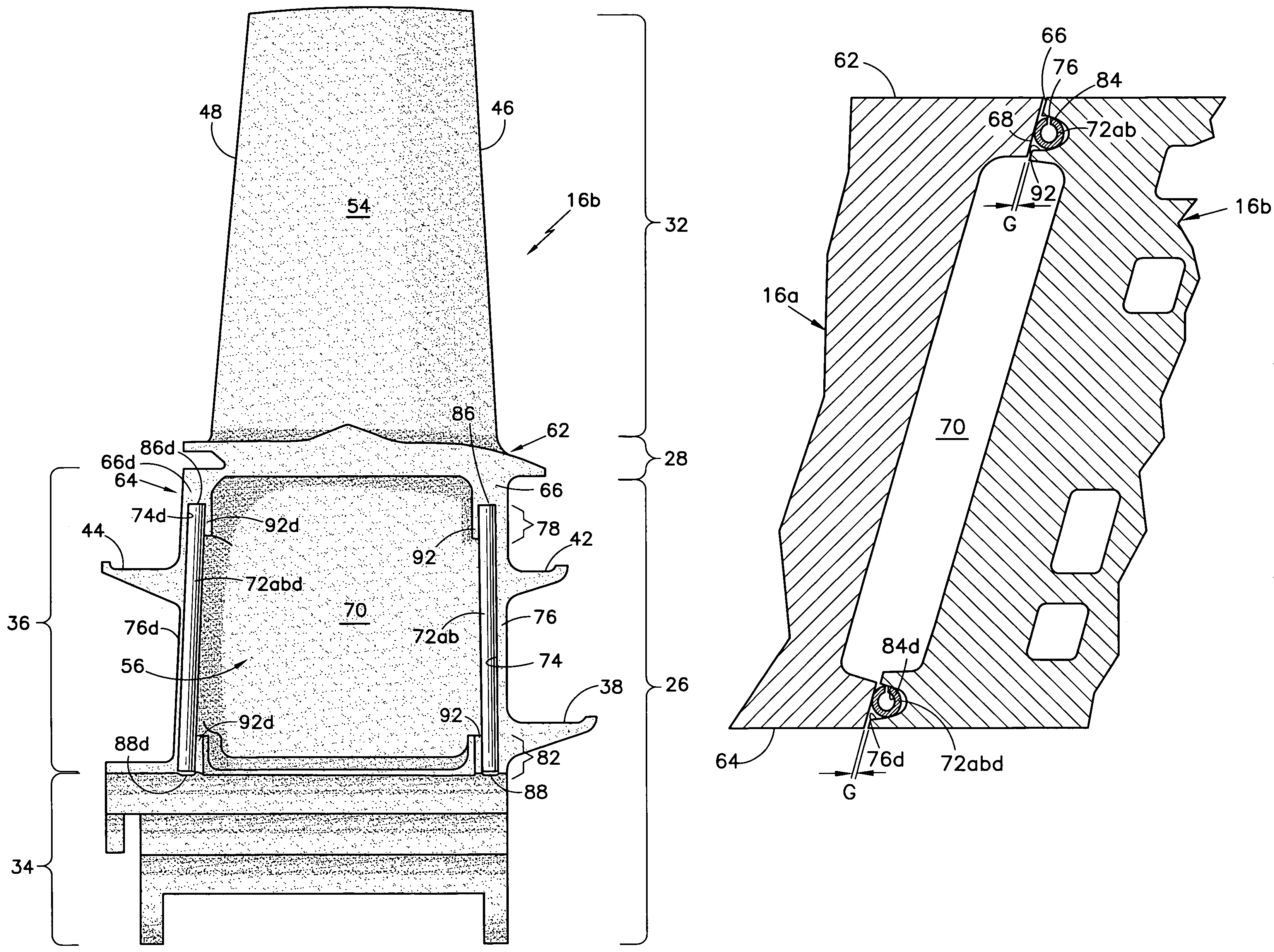
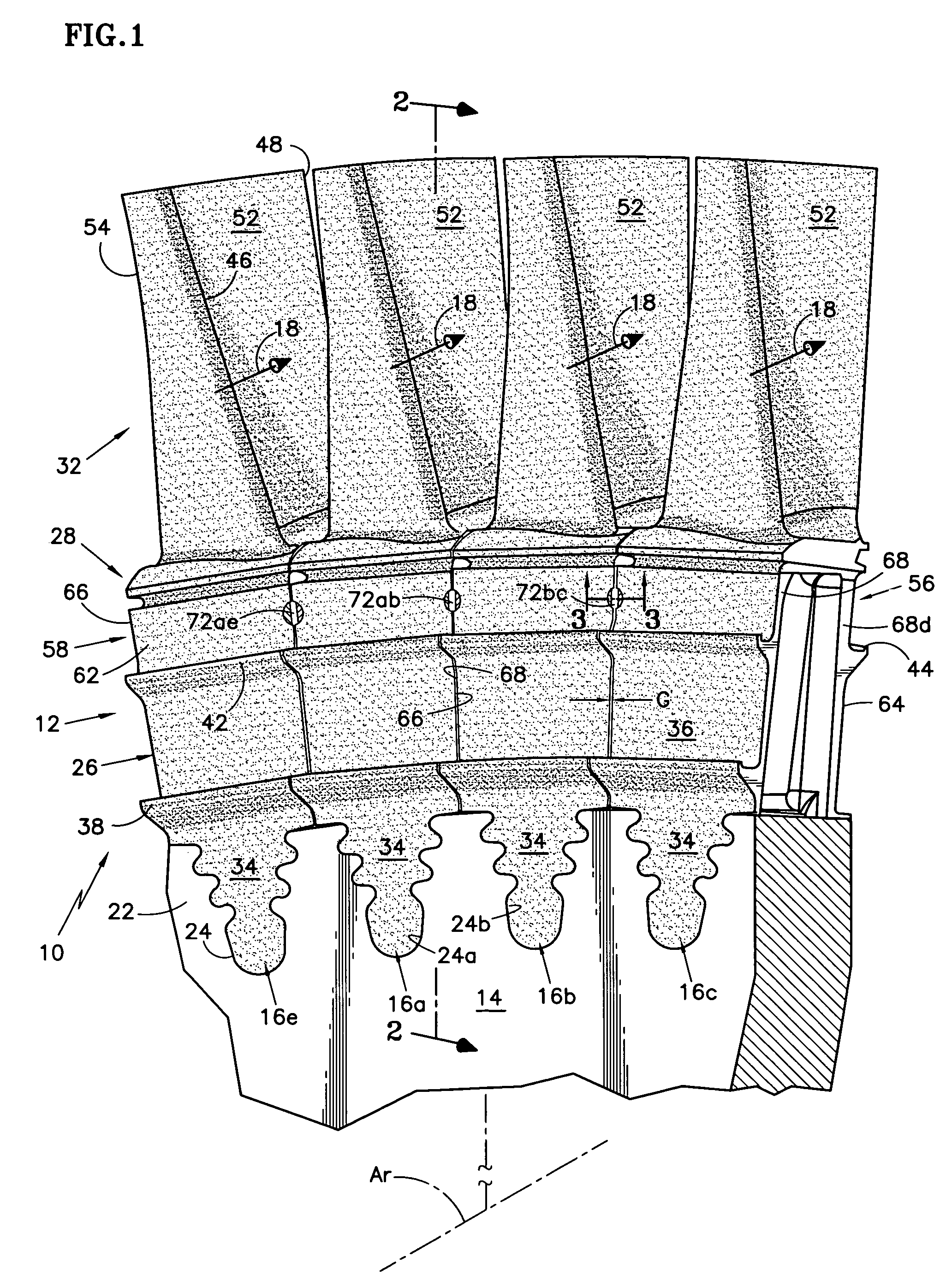
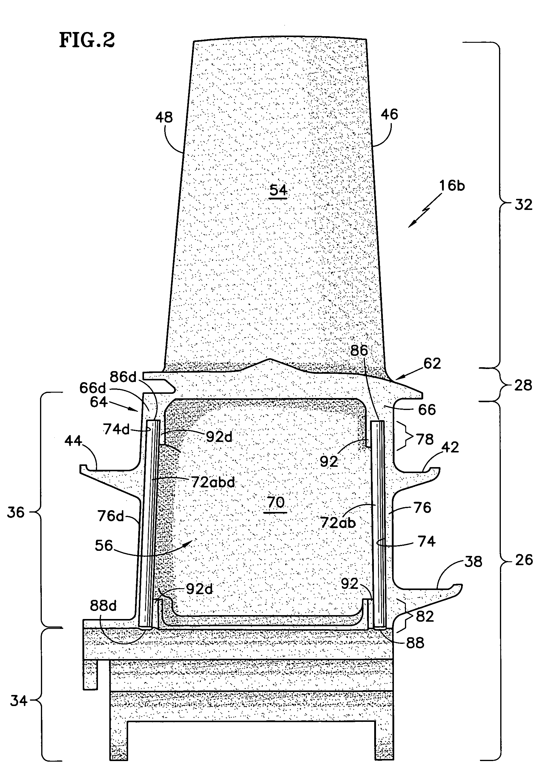
[0025]FIG. 1 shows a portion of a gas turbine engine embodiment of a rotary machine 10. More particularly, FIG. 1 is a schematic, perspective view partially broken away to show a portion of a rotor assembly 12. The rotor assembly extends circumferentially about an axis of rotation Ar. The rotor assembly includes a rotor disk 14 and an array of rotor blades 16, as represented by the plurality of rotor blades 16a, 16b, 16c, 16e. A flow path 18 for working medium gases extends axially through the rotor blades of the rotor assembly.

[0026]The rotor disk 14 includes a rim 22 having a plurality of axially oriented slots, as represented by the fir tree slots 24, which adapt the rotor disk to receive the array of rotor blades 16. Each rotor blade has a root section 26, a platform section 28 and an airfoil section 32. The airfoil section extends outwardly with respect to the root section into the working medium flow path 18.

[0027]The root section 26 has a rotor blade root 34 for engaging a co...


PUM


Abstract

A rotor assembly having a seal member in the root section of a rotor blade is disclosed. Various construction details are developed for blocking the flow of gases between adjacent rotor blades. In one detailed embodiment, a deformable seal member formed of a high temperature material is disposed between the root sections of adjacent rotor blades and engages the blades under operative conditions.

Description

BACKGROUND OF THE INVENTION[0001]This invention relates to rotor assemblies of the type used in rotary machines, such as gas turbine engines, that have rotor blades. More particularly, this invention relates to structure for blocking the flow of gases between the root sections of adjacent rotor blades.[0002]Axial flow gas turbine engines for industrial purposes and for propelling aircraft typically have a compression section, a combustion section and a turbine section disposed about an axis of rotation. An annular flow path for working medium gases extends axially through the sections of the engine. The gases are compressed in the compression section. Energy is added to the gases in the combustion section. The hot working medium gases are expanded through the turbine section.[0003]In the turbine section, the rotor assembly has a rotor disk and rotor blades that extend outwardly from the rotor disk. The rotor blades extend across the flowpath for working medium gases. Each rotor blad...

Claims


Application Information

Patent Timeline
Patent Type & Authority Patents(United States)
IPC IPC(8): F01D5/30
CPCF01D11/008F01D5/3007F01D11/006
Inventor FUNK, STANLEY J.CHLUS, WIESLAW A.
Owner RTX CORP
Why Eureka
Try Eureka