Exhaust cleaning device of diesel engine

a cleaning device and diesel engine technology, applied in the direction of engines, machines/engines, mechanical equipment, etc., can solve the problems of difficult to precisely judge the dpf regenerating period, difficult to univocally presume the integrating pm amount, and fuel cost becomes worse, so as to reduce the regenerating frequency of the filter and improve the corresponding fuel cost

Inactive Publication Date: 2009-08-25
SUBARU CORP
View PDF6 Cites 6 Cited by
  • Summary
  • Abstract
  • Description
  • Claims
  • Application Information

AI Technical Summary

Benefits of technology

[0012]In consideration of the above situation, an object of the present invention is to provide an exhaust cleaning device of the diesel engine able to always precisely judge the regeneration period of the filter for catching and collecting the particulate matter within the exhaust gas by correcting the dispersion of the engine, and able to improve fuel cost by reducing regeneration processing frequency.
[0023]In accordance with the present invention, the regenerating period of the filter is judged on the basis of two judging conditions of the operating state of the diesel engine and the state of the filter. When it is judged as the regenerating period in at least one of these conditions, the regeneration processing of the filter is performed. Further, the first threshold value for judging whether the integrating amount of the particulate matter reaches the regenerating period or not is variably set every regeneration processing. Accordingly, a detection error due to dispersion of the engine is corrected. As its result, the regenerating period of the filter can be always precisely judged. Further, since the regenerating period of the filter is precise, regenerating frequency of the filter is reduced and fuel cost can be correspondingly improved.

Problems solved by technology

It is difficult to univocally presume the integrating PM amount on the basis of the operating state of the engine since there is dispersion in the engine.
Accordingly, it is difficult to precisely judge the DPF regenerating period.
Therefore, a problem exists in that fuel cost becomes worse.
On the other hand, when DPF is judged from the state within the exhaust passage, it is difficult to clearly distinguish a state causing no clogging and a state generating the clogging.
When the regeneration processing after it exceeds the limit of the PM integrating amount is repeatedly performed, a problem exists in that deterioration of DPF is promoted and a reduction of durability is caused.
Therefore, this dispersion of the engine cannot be absorbed, and it is difficult to precisely judge the DPF regeneration period.
Therefore, the DPF regeneration period is easily missed.

Method used


Image

  • Exhaust cleaning device of diesel engine
  • Exhaust cleaning device of diesel engine
  • Exhaust cleaning device of diesel engine

Examples


Embodiment Construction

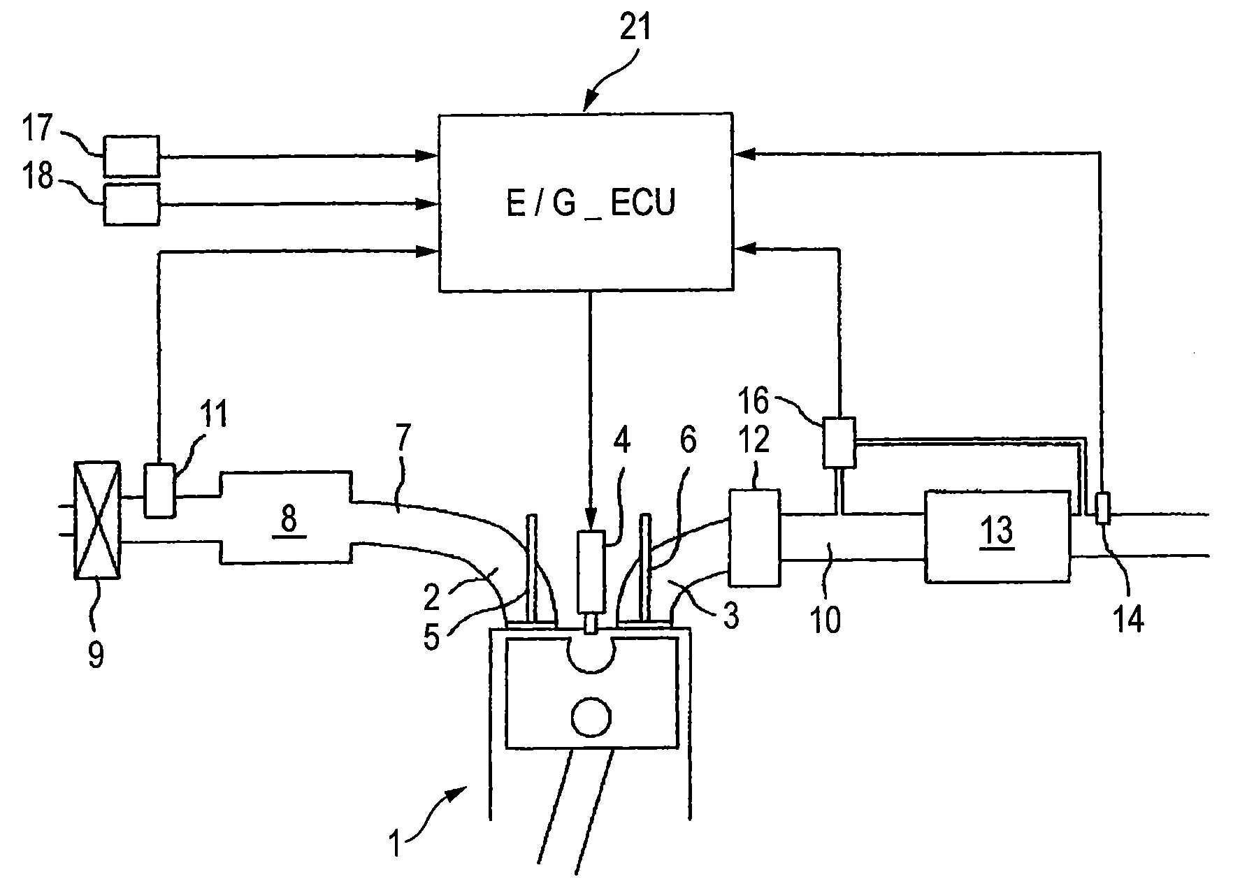
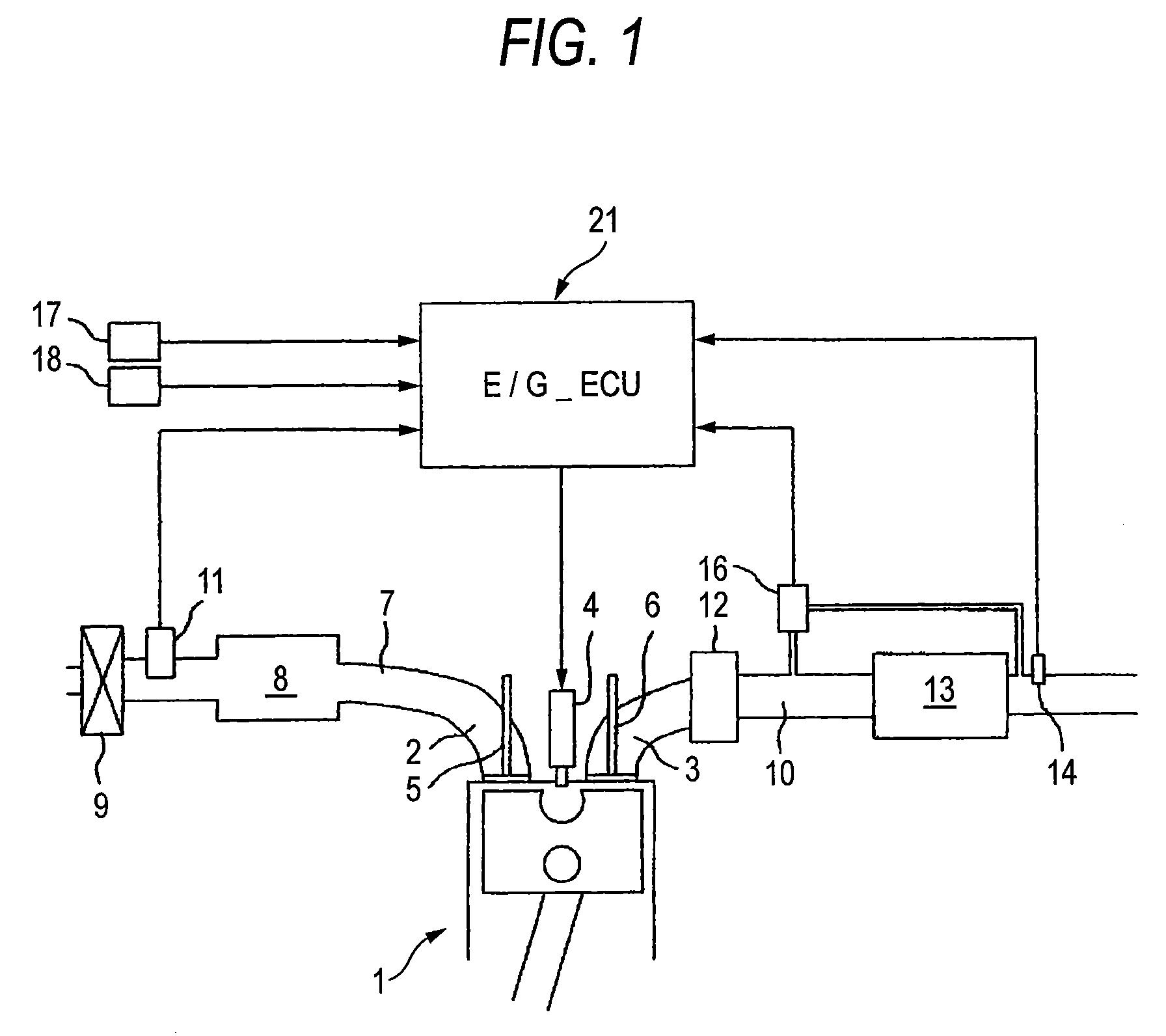
[0041]One mode of the present invention will next be explained on the basis of the drawings. FIGS. 1 to 8 show a first mode of the present invention. FIG. 1 is a schematic constructional view of a diesel engine.

[0042]Reference numeral 1 of FIG. 1 designates an engine main body of the diesel engine. An intake air port 2 and an exhaust port 3 are opened to an upper portion of a combustion chamber of this engine main body 1, and an injector 4 faces this upper portion. Reference numeral 5 designates an intake air valve and reference numeral 6 designates an exhaust valve.

[0043]Further, an intake air passage 7 is communicated in an upper stream of the intake air port 2, and an intake air chamber 8 is formed in an intermediate portion of the intake air passage 7. Further, an air cleaner 9 is attached to an air taking-in port of this intake air passage 7. An intake air amount sensor 11 for detecting an intake air amount faces a stream just below the air cleaner 9.

[0044]Further, an exhaust p...


PUM


Abstract

An integrating PM amount σ PM as an integrating value of a PM generating amount after DPF regeneration is read (S1). The integrating PM amount and a first threshold value SL1 set in advance are compared, and the regenerating period of DPF 13 is judged (S2). Further, a differential pressure ΔPdf before and after DPF 13 detected by a differential pressure sensor 16, and a second threshold value SL2 are compared, and the regenerating period of DPF 13 is judged (S5). Regeneration processing of DPF 13 is then performed when the integrating PM amount σ PM attains the first threshold value SL1 or tore, or the differential pressure ΔPdf attains a second threshold value SL2 or more (S7).

Description

BACKGROUND OF THE INVENTION[0001]The present invention relates to an exhaust cleaning device of a diesel engine able to precisely judge a regenerating period of a filter for catching and collecting a particulate matter within exhaust gas.[0002]The disclosure of Japanese Patent Application No. 2006-106674 filed on Apr. 7, 2006 including the specification, drawings and abstract is incorporated herein by reference in its entirety.[0003]In the diesel engine, the particulate matter (PM) included within the exhaust gas is conventionally caught and collected by a filter (DPF: Diesel Particulate Filter) interposed in an exhaust passage. In DPF, the flowed-in exhaust gas passes a porous partition wall and PM is caught and collected by a surface of the partition wall and a fine hole.[0004]PM caught and collected in DPF is deposited with the passage of time. Therefore, after PM reaches a predetermined amount, regeneration processing for removing PM is performed for the purpose of prevention of...

Claims


Application Information

Patent Timeline
Patent Type & Authority Patents(United States)
IPC IPC(8): F01N3/00
CPCF01N9/002Y02T10/47F01N2550/04Y02T10/40
Inventor OHMURA, YASUSHI
Owner SUBARU CORP
Why Eureka
Try Eureka