
Vehicle mud flap with fender fold clamp

a technology of fender and fender, which is applied in the direction of vehicle components, children carriages/perambulators, superstructure sub-units, etc., can solve the problems of voiding the oem corrosion warranty, unable to affix mud flaps to vehicles without drilling such holes, and unable to meet the requirements of vehicle fender and fender fender fender fender fender,

Active Publication Date: 2009-08-25
MACNEIL IP
View PDF33 Cites 24 Cited by
  • Summary
  • Abstract
  • Description
  • Claims
  • Application Information

AI Technical Summary

Benefits of technology

The solution provides a secure and safe attachment of mud flaps to vehicle wheel wells without drilling, preventing corrosion and ensuring the mud flaps remain firmly in place at high speeds, thus enhancing safety and maintaining the vehicle's corrosion warranty.

Problems solved by technology

As it rotates on a surface each wheel (particularly if it is a drive wheel) will have a tendency to kick up tar, water, mud, stones and debris onto the vehicle body panel or rearwardly into the path of traffic behind the vehicle.
While the use of through-fasteners through such holes usually will assure firm affixation of the mud flap to the vehicle, drilling the holes creates a serious corrosion problem and may void the OEM corrosion warranty.
Prior attempts to affix mud flaps to vehicles without drilling such holes have been less than satisfactory.
As can be imagined, a mud flap dropping off of a vehicle at Interstate highway speeds creates a serious safety issue.

Method used


Image

  • Vehicle mud flap with fender fold clamp
  • Vehicle mud flap with fender fold clamp
  • Vehicle mud flap with fender fold clamp

Examples


Embodiment Construction

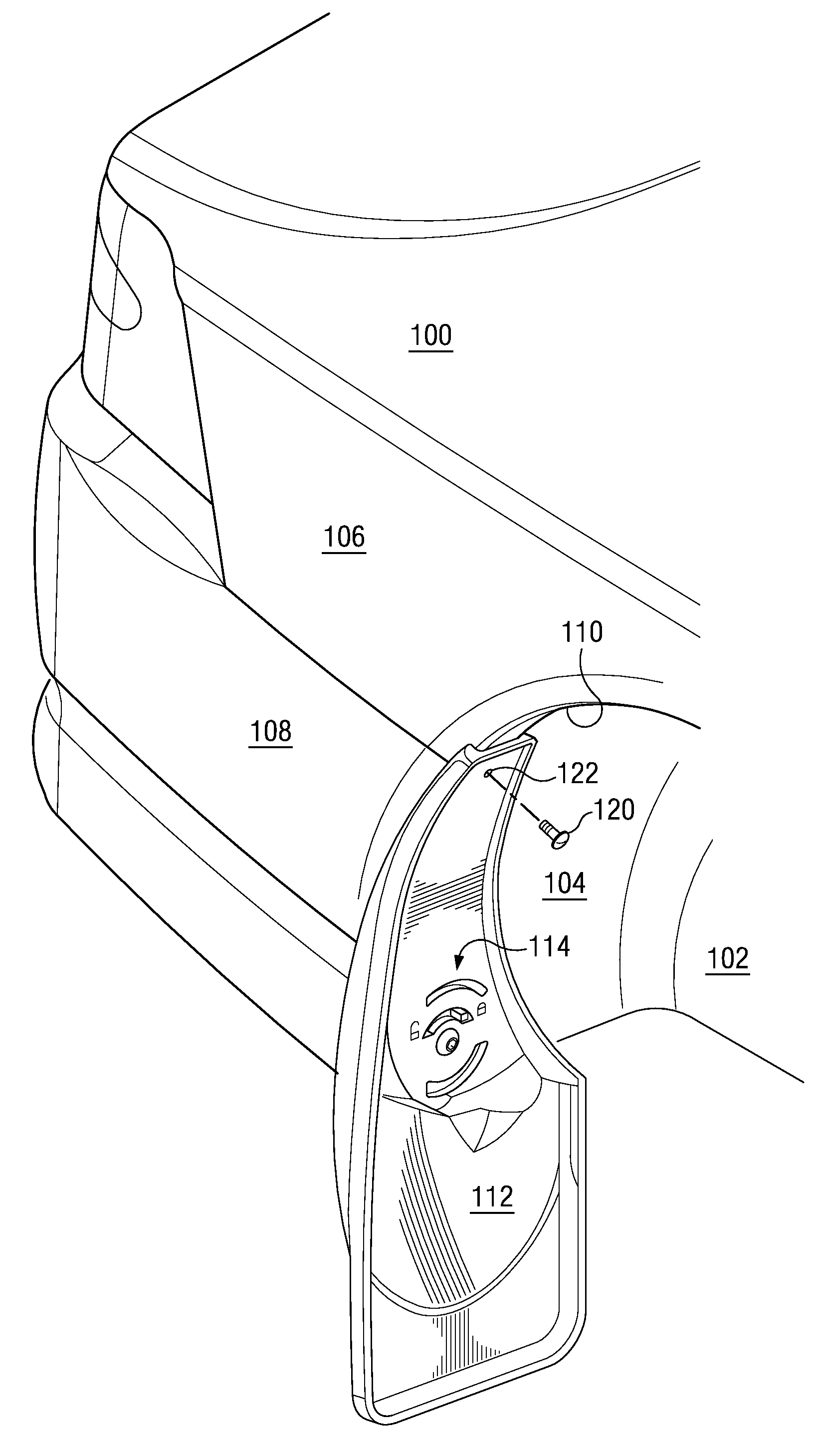
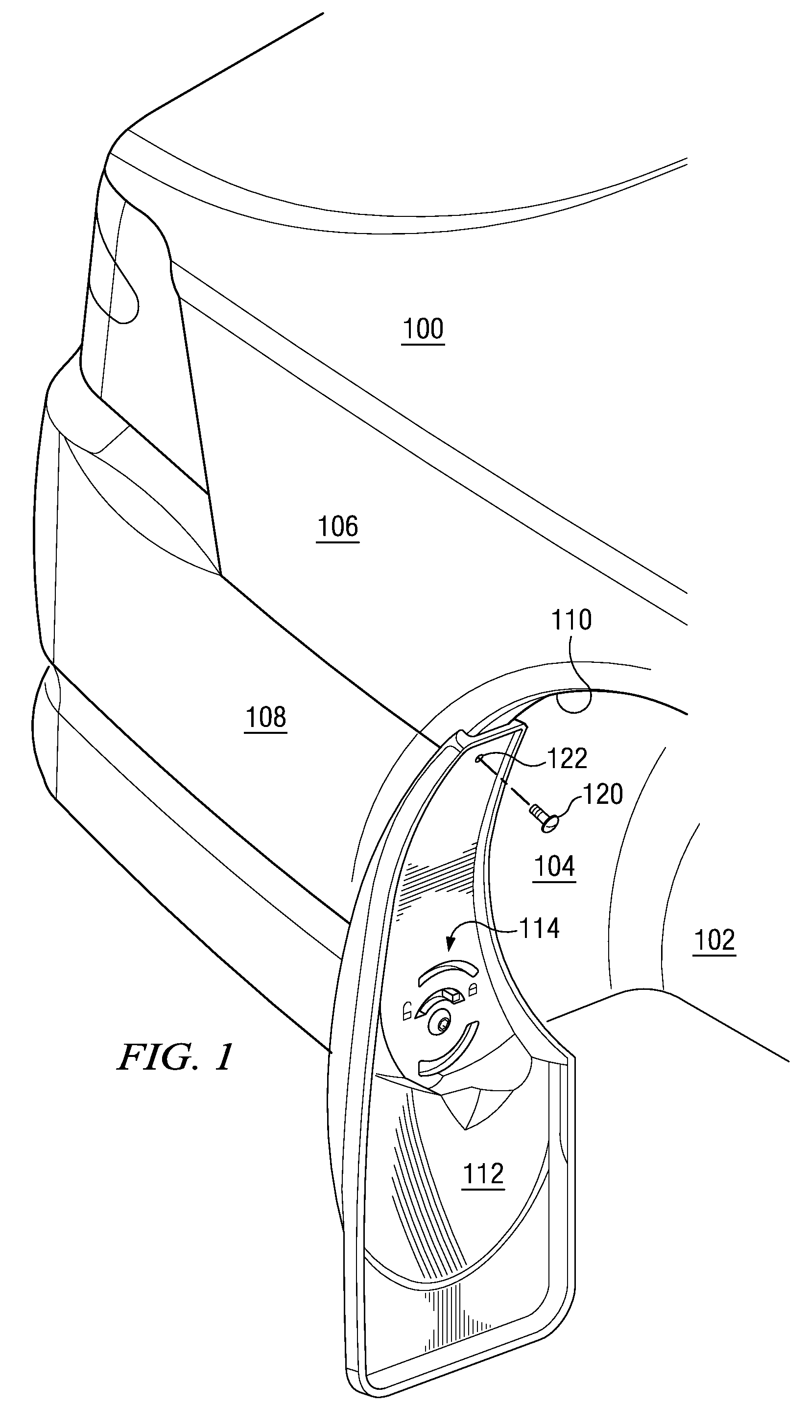
[0019]FIG. 1 shows a conventional vehicle 100 with a wheel well 102. The wheel well 102 typically has a rear curved surface 104 that conforms approximately to a cylinder. The body 106 of the vehicle 100 is typically formed of one or more panels 108 of sheet steel which have been coated with an anticorrosion coating and painted; in certain vehicle models this sheet steel is replaced with another sheet material, such as plastic, aluminum or a fibrous composite. One or more such panels 108 are disposed to be adjacent the wheel well 102. At the juncture of the wheel well 102 and the panel 108, commonly the panel 108 is bent or folded in an inboard direction to make a fender fold or lip 110. This fender fold 110 follows curved surface 104 around at least a large portion of the wheel well 102.

[0020]A mud flap 112 according to the invention is affixed to a rearward portion of the curved surface 104, and is particularly placed such that an edge or portion of the mud flap 112 adjoins and is ...


PUM


Abstract

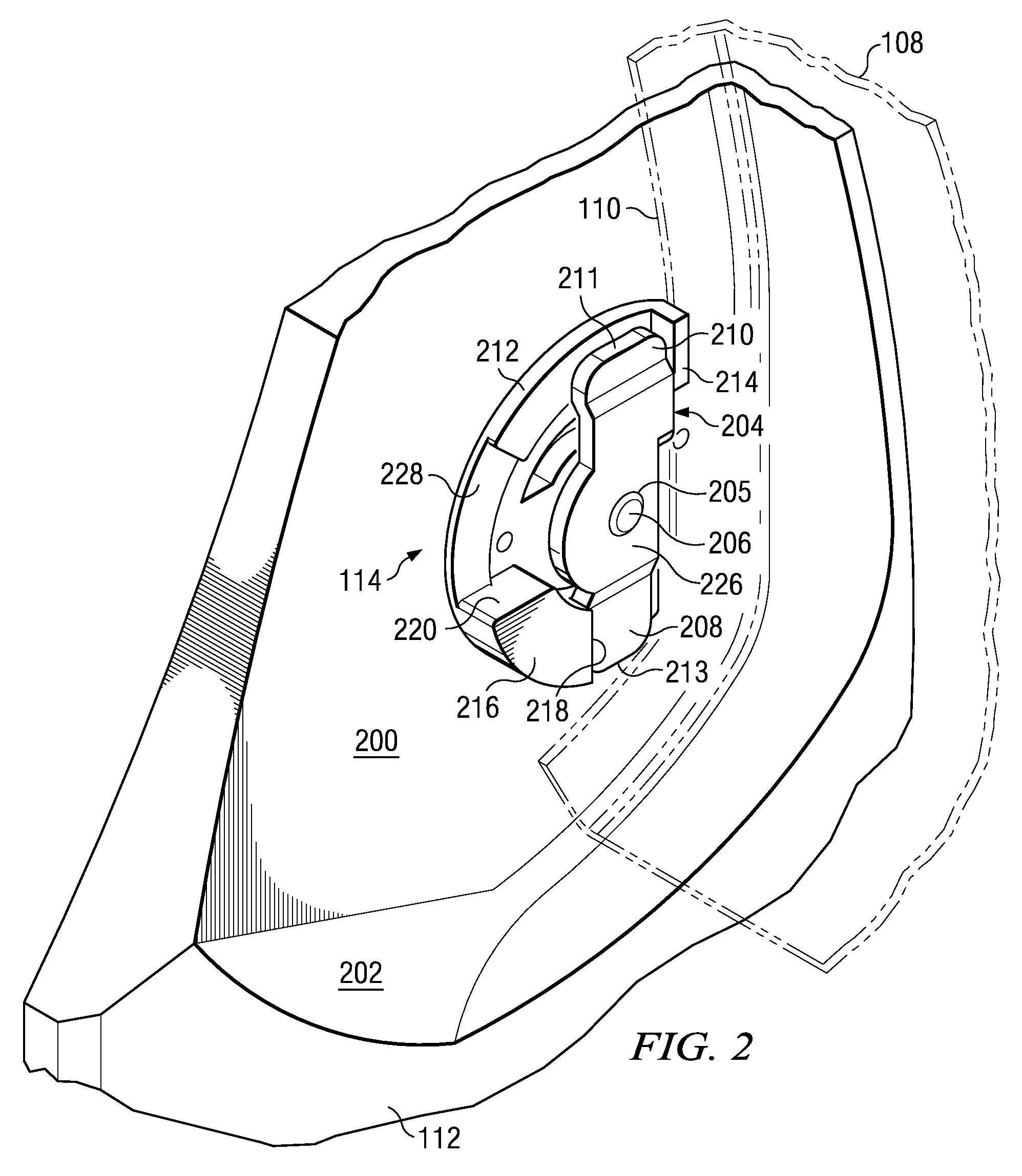
The drilling of new holes into a vehicle fender fold is avoided by providing a mud flap with a rotating clamping member. A clamping arm of the rotating clamping member is rotated from a disengaged position to an engaged position behind the fender fold, and is then drawn forwardly on the threads of an attachment bolt to clamp the fender fold between the rotating clamping member and a stationary clamping member in-molded into the mud flap. A visual indicator may be provided to show whether the rotating clamping member is behind the vehicle fender fold to which the mud flap is to be attached.

Description

BACKGROUND OF THE INVENTION[0001]Conventional motor vehicles have tires partly recessed in wheel wells. Of course the tire extends below, and often far below, the bottom body panel of the vehicle. As it rotates on a surface each wheel (particularly if it is a drive wheel) will have a tendency to kick up tar, water, mud, stones and debris onto the vehicle body panel or rearwardly into the path of traffic behind the vehicle.[0002]To mitigate this problem, mud flaps have been devised which attach to the rear of each wheel well and which extend downward toward the road surface, intercepting much of the matter spinning off of the wheel. Many of these mud flaps have been designed for the automotive aftermarket, in which a vehicle owner will attach the mud flap to the wheel well himself or herself. Prior automotive mud flaps have required further holes to be drilled into the flange called a “fender fold” or lip, which is an extension of the vehicle body panel that skirts the wheel well and...

Claims


Application Information

Patent Timeline
Patent Type & Authority Patents(United States)
IPC IPC(8): B62D25/18
CPCB62D25/182
Inventor IVERSON, DAVIDMACNEIL, DAVID F.
Owner MACNEIL IP
Learn More