
Light shaping reflector system and method of manufacture and use

a technology of reflectors and reflectors, applied in semiconductor devices, lighting and heating apparatus, light source applications, etc., can solve problems such as molded optical, challenge or obsolete existing optics, and refractive designs with wide angles or multiple angles

Inactive Publication Date: 2009-08-25
INTENCITY LIGHTING
View PDF10 Cites 22 Cited by
  • Summary
  • Abstract
  • Description
  • Claims
  • Application Information

AI Technical Summary

Benefits of technology

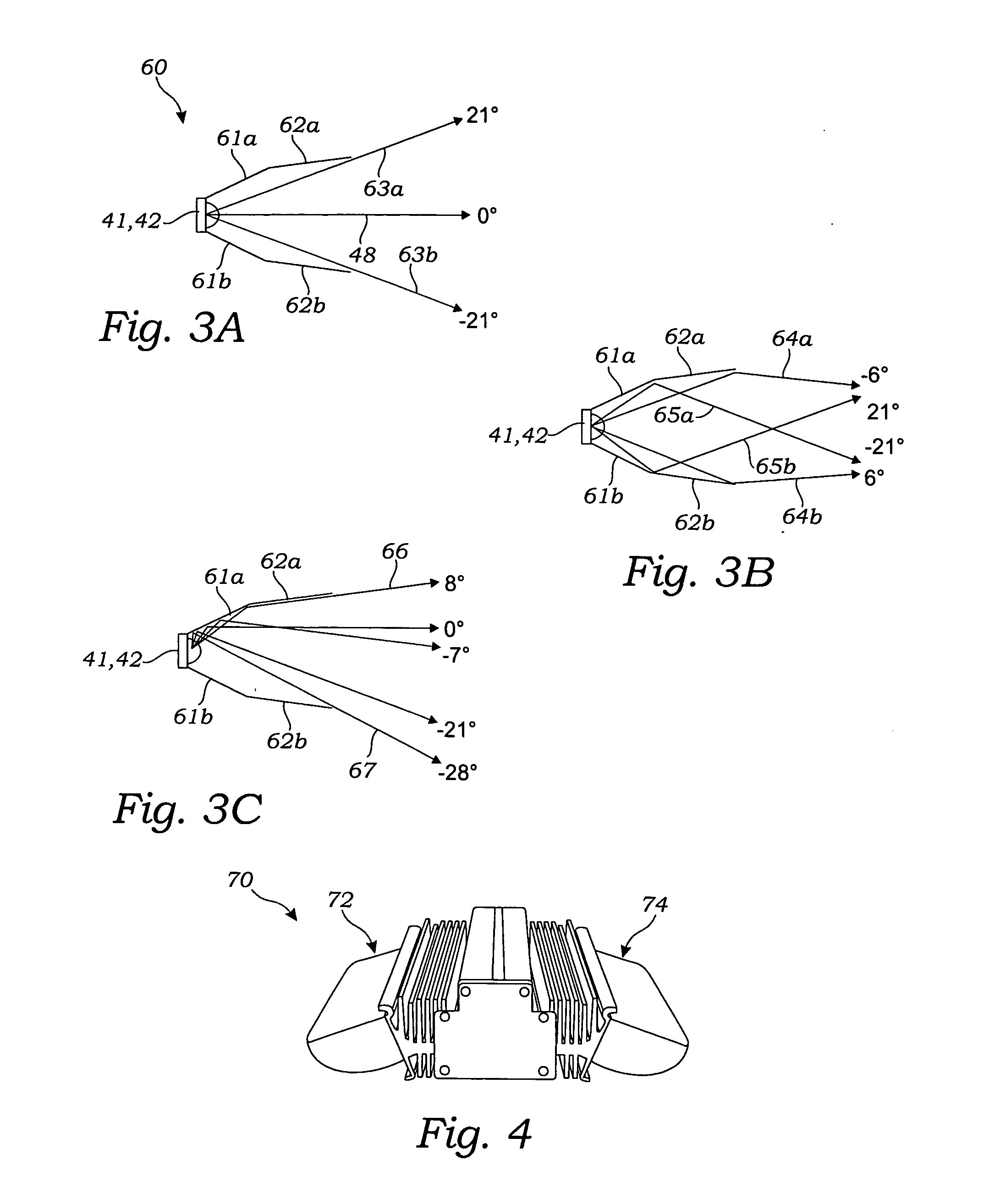
[0017]Aspects of the present invention are directed to light sculpting and beam shaping for an individual LED or for a plurality of LED light sources while affixed to heat sinks or circuit boards. In an exemplary embodiment, the resulting reflector aligns approximately one-half of its light source, hereinafter referred to as “upper LEDs,” within rectangular multi-angle reflectors to collimate or amplify one axis of those light rays that follow or approximate the angles of maximum candela in order to maximize light projection toward the farthest illumination areas of the target. In the case of a single LED, the reflector dissects and directs approximately one-half of the light source. The multiple angles in each of four sides of the exemplary reflector will collect nearly all remaining non-collimated light rays from the upper light source and will shape and redirect this light toward the areas within and adjacent the specified far field points to fill the subject area with luminance. The remaining approximately one-half of the light source, hereinafter referred to as “lower LEDs,” may be directed to illuminate targets beneath and near the luminaire, without refraction, and follow the selected cut-off angles of the reflector that is positioned above the “lower LEDs.” Accordingly, aspects of the reflector of the present invention allow the “lower LEDs” to directly illuminate nearby areas and, in aligning the optical axis of the “lower LEDs” with the same optical axis of the “upper LEDs,” to capture at least four sides of the upper LED light rays for far field targets, whereby using off-axis rays with near targets allows an even greater brightness toward the distant target to be achieved.
[0018]Further aspects of the present invention teach a reflector system that conforms LED light emissions to a plurality of standards by substitution of only a few parts. Those skilled in the art will appreciate that various illumination standards may be met by changing a segment of a reflector angle or dimension. Aspects of the reflector system of the present invention can control or “cut off” multiple axis emissions from one LED or from a plurality of LEDs by moving the reflective angle and position relative to the LED. The reflector is sufficiently small to enable close proximity of high-output LEDs within an array, and by substituting different vanes, a large number of beam variations and shapes are possible. As such, the reflector system of the present invention can be adapted to numerous lighting standards by changing only the size and position of universal, simple and economical parts that are used in a plurality of product styles.
[0019]Aspects of the exemplary reflector system of the present invention further allow collimation or amplifying for light projection without the use of refraction lenses. As such, the LED lighting system may be encased beneath a single optically clear non-refracting window. It is known that the absence of refractive lenses in the window will yield higher optical efficiency and permit the same production window to be used with all like products regardless of their variations in light pattern distribution.
[0020]In a further aspect of the invention, the reflector provides two-axis control through which beam collimation and wide-angle beam overlapping occur by design to combine wide angle light rays that can be a different correlated color temperature (“CCT”) than on-axis rays of that same LED. Accordingly, aspects of the present invention allow for the adjustment of color temperature by blending the various color temperatures from the same LED without the need to externally mix LED families.
[0021]Yet further aspects of the light shaping reflector system and method of the present invention provide for the customization of each axis of the reflector by changing only the laser-, water-jet-, die- or other such cutting of the flat pieces of reflective material from which the reflector is ultimately formed and / or by changing the subsequent bending and forming steps applied to the flat pieces. Those skilled in the art will appreciate that laser, water-jet, die-cutting and other such fabrication methods taught by the present invention can quickly provide optical solutions in which there is no significant difference between prototype and production grade optical quality. Further, laser- and water-jet-cutting methods particularly are known to be fractions of the cost, waste less material and be more accurate than die-cut and other production methods.

Problems solved by technology

In the context of indoor and outdoor lighting, one challenge in connection with the use of such “high-output LEDs” is collecting and reshaping the light to efficiently illuminate the areas and shapes required by industry lighting standards and the application.
Refractive designs for wide angles or multiple angles or sharp bending will typically suffer losses due to internal reflections within the refractive lens.
It is known that LED manufacturers are getting more light output with phosphor deposition and optical techniques that don't necessarily conform to true Lambertian or standard emission patterns, which can challenge or obsolete existing optics already set by LED integrators.
Mass production of a molded optical solution, whether the system is optically refractive with an injection-molded lens or reflective with a deposited metalized finish on a molded substrate, requires intricate tooling and a highly polished mold.
Such tools, though capable of mass production, are relatively expensive.
Alternately, rapid prototyping methods through which a single part may be fabricated, though capable of smaller quantity production, ultimately cost even many times more than that of a mass production part while still requiring polishing.
Either process can take several months or more to complete.
While asymmetrical optics may also be accomplished in molded refractive or reflective parts by adding or removing curvature or angle on a side of the mold, however, this does cause other complications as known in the art: (1) each half of the illumination task of the streetlight requires a different or mirror image mold, likely to require additional financial investment as well, and (2) draft angles and often necessarily symmetrical mold geometry can complicate some asymmetrical parts fabricated with a conventional release mold without special gates or slides, potentially adding further cost and delay to mold fabrication.
Furthermore, LED integrators often mix colors of LEDs to affect different CCT, which can be problematic since LED family characteristics vary differently with time and environment.
The prior art described above teaches various shaped reflectors formed from various materials and manufacturing methods, but does not teach a reflector system having two-axis control through which beam collimation and wide-angle beam overlapping occur or a method of manufacturing such a system through cutting flat reflective sheeting via laser, water-jet, die, or other such technique to form the resultant flat parts into the three-dimensional reflectors that collect and shape light from solid state LEDs, wherein each axis may be customized by changing only the laser, water-jet, die or other such cutting, bending, or shaping of the flat pieces.

Method used


Image

  • Light shaping reflector system and method of manufacture and use
  • Light shaping reflector system and method of manufacture and use
  • Light shaping reflector system and method of manufacture and use

Examples


Embodiment Construction

[0040]The above described drawing figures illustrate aspects of the invention in at least one of its exemplary embodiments, which are further defined in detail in the following description.

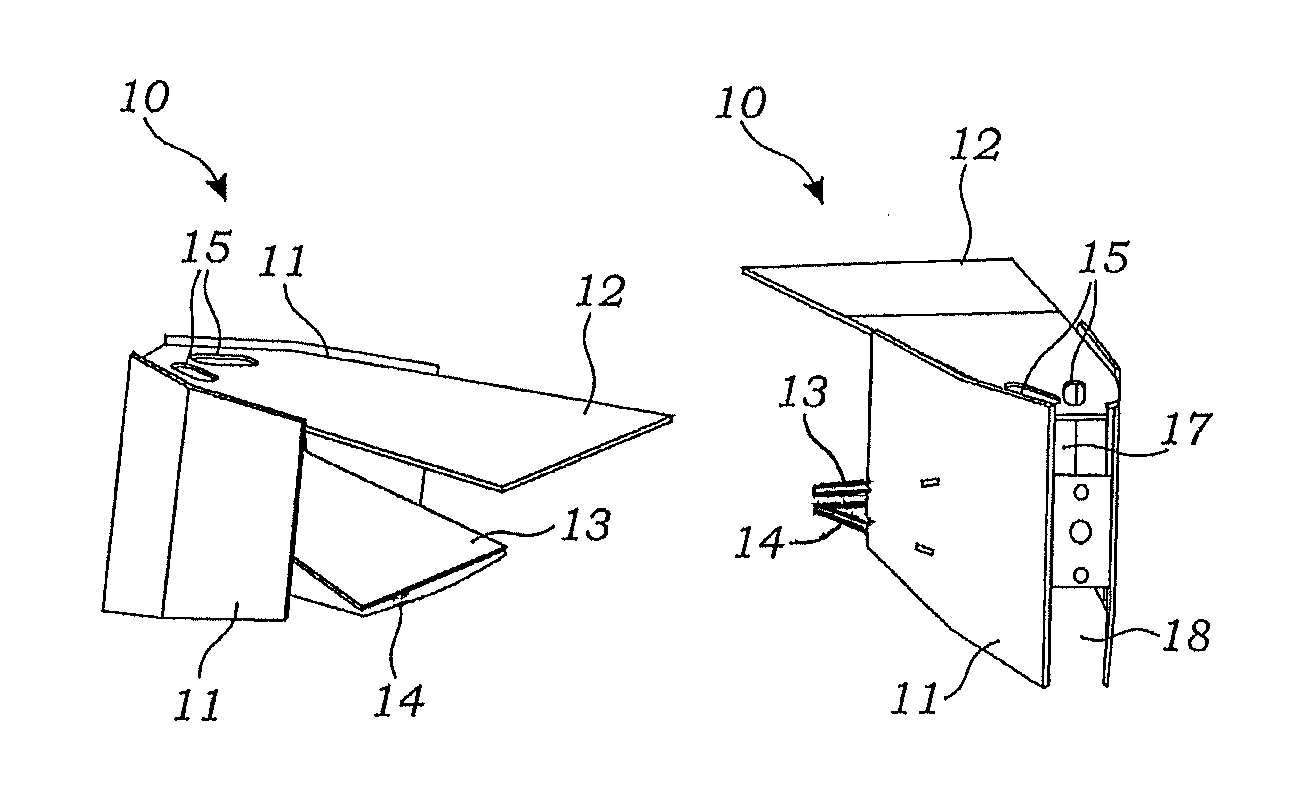
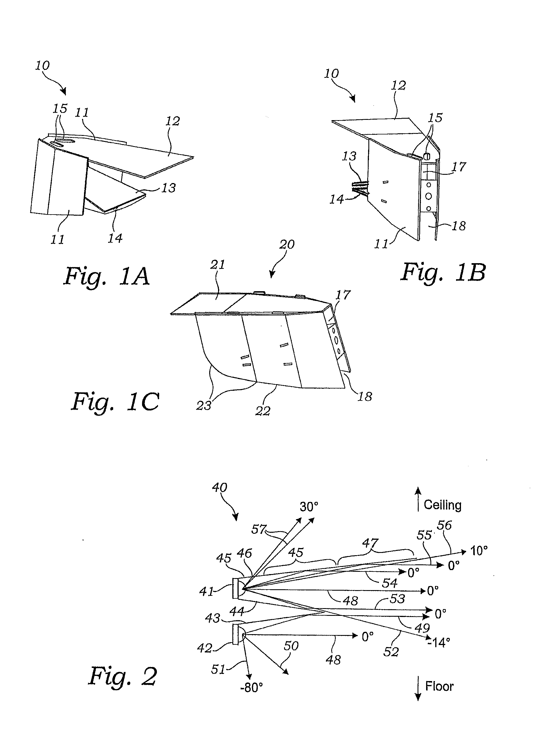
[0041]Turning first to FIGS. 1A-1C, there are shown exemplary embodiments of the reflector of the present invention. In FIGS. 1A and 1B, an exemplary parking garage reflector 10 is shown from the right and the rear, respectively, and in FIG. 1C, a side perspective view of a streetlight reflector 20 is shown. Referring to FIG. 1A there are shown side vanes 11 that wrap around a top vane 12, an upper intermediate vane 13 and a spaced apart lower intermediate vane 14 to form the reflector 10. The upper slots 15 formed in the top vane 12 allow some light to pass upward from at least the upper LED 41 (FIG. 2) toward a ceiling (not shown), more about which is explained below. In FIG. 1B of the rear of the reflector assembly 10, there is again shown the side vanes 11, which can now be seen as having a sp...


PUM


Abstract

A reflector system having two-axis control through which beam collimation and wide-angle beam overlapping occur, and a method of manufacturing such a system through cutting flat reflective sheeting and forming the resultant flat parts into the three-dimensional reflectors that collect and shape the light from solid state LEDs, wherein each axis may be customized by changing the cutting and bending of the flat pieces.

Description

RELATED APPLICATIONS[0001]This application claims priority and is entitled to the filing date of U.S. Provisional Application Ser. No. 60 / 714,218 filed Sep. 3, 2005, and entitled “LIGHT SHAPING REFLECTOR SYSTEM FOR LIGHT EMITTING DIODES.” The contents of the aforementioned application are incorporated by reference herein.INCORPORATION BY REFERENCE[0002]Applicants hereby incorporate herein by reference any and all U.S. patents and U.S. patent applications cited or referred to in this application.BACKGROUND OF THE INVENTION[0003]1. Field of the Invention[0004]Aspects of this invention relate generally to systems for shaping light emission patterns of solid state lighting units or assemblies, and more particularly to systems for shaping the light emitted from Light Emitting Diodes (“LEDs”) used in indoor or outdoor lighting units.[0005]2. Description of Related Art[0006]LEDs are now available in high power packages that provide high lumen output from a single source. In the context of ...

Claims


Application Information

Patent Timeline
Patent Type & Authority Patents(United States)
IPC IPC(8): F21V7/00
CPCF21V7/041F21V7/09F21S2/005F21Y2101/02F21W2131/105F21W2131/40F21W2131/103F21Y2115/10
Inventor MULLINS, PATRICK STUARTBRUCK, MICHAEL RAYMOND
Owner INTENCITY LIGHTING
Learn More