Automotive dynamoelectric machine

a dynamoelectric machine and motor technology, applied in the direction of mechanical equipment, bearing unit rigid support, coupling device connection, etc., can solve the problems of the service life of rolling bearings and brushes, etc., and achieve the effect of extending the service life of brushes and rolling bearings

Inactive Publication Date: 2009-08-25
MITSUBISHI ELECTRIC CORP
View PDF16 Cites 8 Cited by
  • Summary
  • Abstract
  • Description
  • Claims
  • Application Information

AI Technical Summary

Benefits of technology

[0007]The present invention aims to solve the above problems and an object of the present invention is to provide an automotive dynamoelectric machine that achieves extension of service life of brushes and rolling bearings, etc., by forming a ventilation channel in a slinger that covers a space around slip rings so as to suppress temperature increases in the slip rings by making a cooling airflow flow through the space in question.
[0009]According to the present invention, the ventilating means makes external air pass between the slinger portion and the rectifier, and also between the bearing accommodating portion and the rectifier, and flow into the housing through the air intake aperture. Here, differential pressure arises between the internal portion and the external portion of the slinger portion, the external air flows into the slinger through the first ventilation channel, and air inside the slinger flows out through the first ventilation channel, replacing air in a space around the slip rings inside the slinger with external air. Thus, temperature increases in the slip rings and the brushes are suppressed, and temperature increases in the bearing, which is disposed in close proximity to the slip rings and the brushes, are also suppressed, enabling the service life of the brushes and the rolling bearing to be extended.

Problems solved by technology

In conventional automotive alternators, because the rolling bearings, the slip rings, and the brushes, etc., are disposed in close proximity, service temperatures of each of these parts have been increasing in recent years with increases in automotive alternator output, and effects thereof on the service life of the rolling bearings and the brushes, etc., have become a problem.

Method used


Image

  • Automotive dynamoelectric machine
  • Automotive dynamoelectric machine
  • Automotive dynamoelectric machine

Examples


embodiment 1

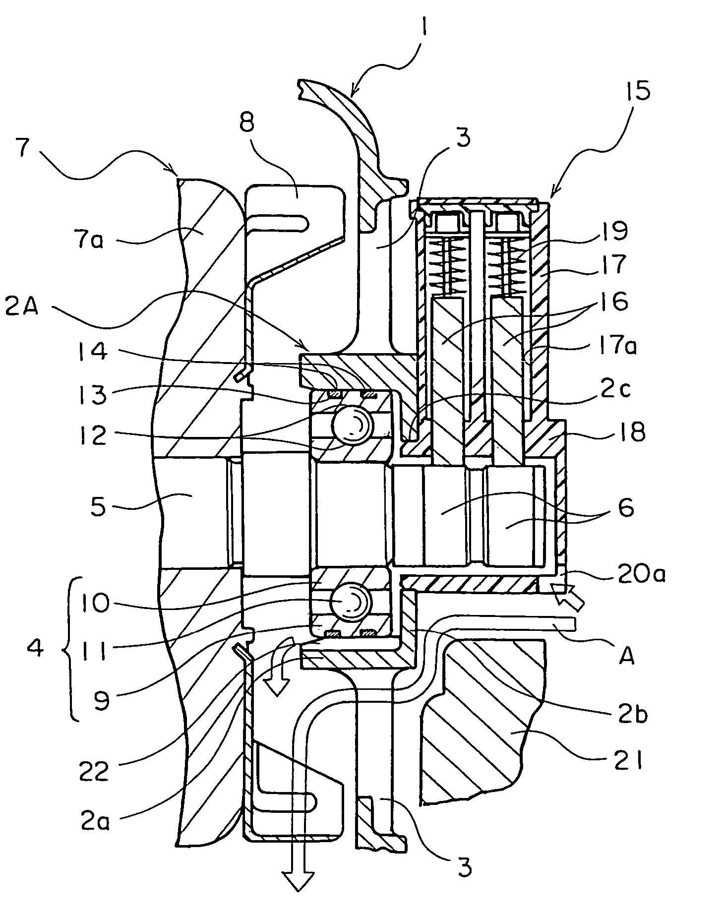
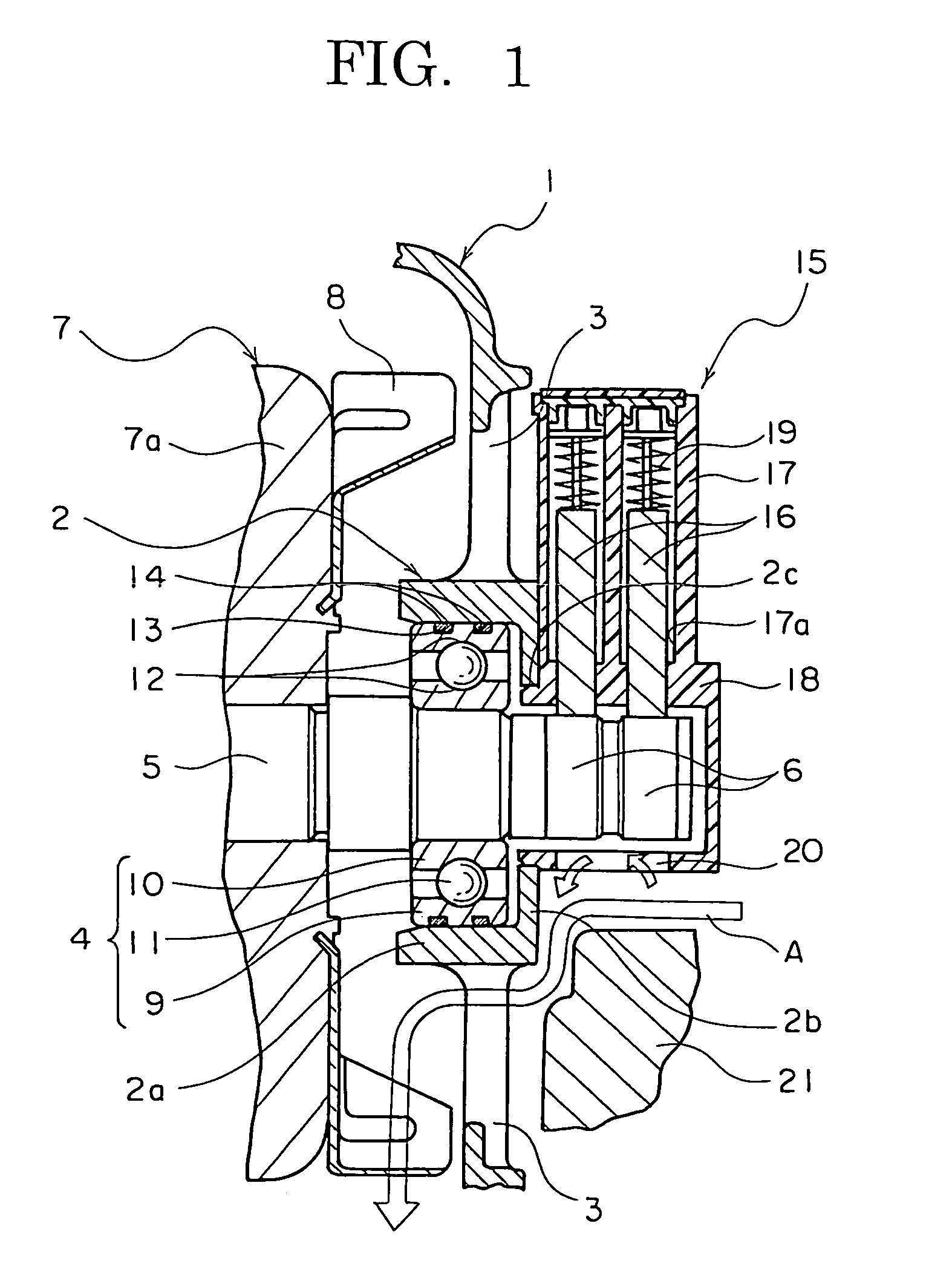
[0017]FIG. 1 is a longitudinal section of part of an automotive dynamoelectric machine according to Embodiment 1 of the present invention.

[0018]In FIG. 1, a rear bracket 1 is made of aluminum that is formed so as to have a bowl shape and a rear-end bearing accommodating portion 2 that has a floored cylindrical shape that is constituted by a cylindrical portion 2a and a floor portion 2b is formed integrally on a central portion of an end surface of the rear bracket 1 such that an open end thereof faces inward. A shaft insertion aperture 2c is disposed through a central portion of the floor portion 2b of the rear-end bearing accommodating portion 2. A plurality of air intake apertures 3 are disposed through the rear bracket 1 in a vicinity of the rear-end bearing accommodating portion 2. Although not shown, a plurality of air discharge apertures are disposed through a side surface of the rear bracket 1.

[0019]Moreover, although not shown, a front bracket that functions together with th...

embodiment 2

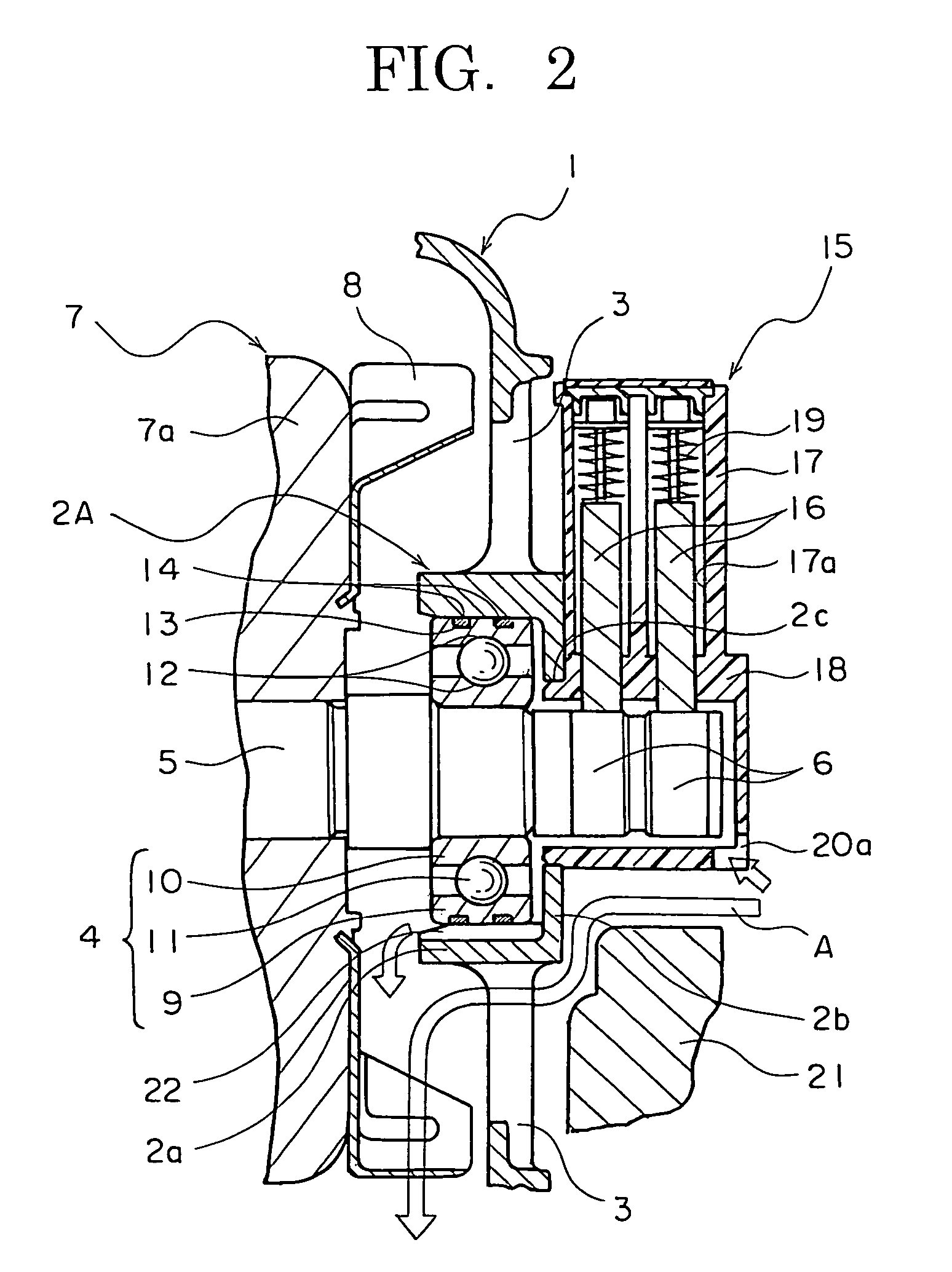
[0039]FIG. 2 is a longitudinal section of part of an automotive dynamoelectric machine according to Embodiment 2 of the present invention, FIG. 3 is a cross section that explains a configuration of a rear-end bearing accommodating portion in the automotive dynamoelectric machine according to Embodiment 2 of the present invention, and FIG. 4 is a partial cross section that shows a state in which a rolling bearing is accommodated in the rear-end bearing accommodating portion in the automotive dynamoelectric machine according to Embodiment 2 of the present invention.

[0040]In FIGS. 2 through 4, a second slit 22 that functions as a second ventilation channel is recessed into an inner wall surface of a cylindrical portion 2a of a rear-end bearing accommodating portion 2A so as to have a groove direction that is aligned in an axial direction of the shaft 5 and so as to extend from a floor portion 2b to an opening. A first slit 20a that functions as a first ventilation channel is disposed t...

embodiment 3

[0048]FIG. 5 is a longitudinal section of part of an automotive dynamoelectric machine according to Embodiment 3 of the present invention.

[0049]In FIG. 5, a third slit 23 that functions as a third ventilation channel is disposed through an intersecting portion between a cylindrical portion 2a and a floor portion 2b of a rear-end bearing accommodating portion 2A so as to be positioned so as to face downward when the automotive dynamoelectric machine is mounted to a vehicle. A second slit 22 and an external portion of the rear-end bearing accommodating portion 2A thereby communicate through the third slit 23.

[0050]Moreover, the rest of this embodiment is configured in a similar manner to Embodiment 2 above.

[0051]In Embodiment 3, when the centrifugal fans 8 are driven, external air passes between the slinger portion 18 and the rectifier 21 and also between the rear-end bearing accommodating portion 2A and the rectifier 21, and is sucked into the housing through the air intake apertures...


PUM


Abstract

A rear-end bearing accommodating portion that has a floored cylindrical shape is formed integrally on a rear bracket. A brush apparatus is mounted to the rear bracket by mounting a slinger portion onto an end portion of a shaft so as to cover slip rings. A rectifier is mounted to the rear bracket in close proximity to the rear-end bearing accommodating portion and the slinger portion. A rolling bearing is configured into a creep preventing bearing in which a resin band is mounted into a ring-shaped recessed groove that is recessed into an outer circumferential surface of an outer ring. A first slit is disposed through the slinger portion so as to be positioned so as to face downward when mounted to a vehicle and so as to communicate between an internal portion and an external portion of the slinger portion.

Description

BACKGROUND OF THE INVENTION[0001]1. Field of the Invention[0002]The present invention relates to an automotive dynamoelectric machine that is mounted to a passenger car, or a truck, etc.[0003]2. Description of the Related Art[0004]In conventional automotive alternators, bearing accommodating portions are configured as separate members from a frame and are mounted to mount surfaces of the frame in a closely-fitted state. Rolling bearings are accommodated in the bearing accommodating portions, and a rotor that generates field magnetic flux is rotatably held by the frame by supporting a rotating shaft thereof in the rolling bearings. Slip rings are mounted to a portion of the rotating shaft that projects through the bearing accommodating portions. A brush apparatus includes: a brush holder that accommodates brushes; and a slip ring cover that covers an outer circumference of the slip rings. Airtightness of a space around the slip rings is maintained by covering the space in question in...

Claims


Application Information

Patent Timeline
Patent Type & Authority Patents(United States)
IPC IPC(8): H02K5/173H02K5/20H02K9/02
CPCH01R39/385H02K13/003H02K5/1732H01R13/6641H02K9/06F16C19/06F16C35/067F16C2226/10F16C2380/26H02K5/141H02K9/28
Inventor MORIKAKU, HIDEKIASAO, YOSHIHITO
Owner MITSUBISHI ELECTRIC CORP
Why Eureka
Try Eureka