System and method for maintaining proper termination and error-free communication in a network bus

a network bus and error-free technology, applied in data switching networks, instruments, high-level techniques, etc., can solve the problems of high cost, high cost, and high cost of dedicated wiring, and achieve the effect of reducing the probability of damage or breakage of some portion of the wiring

Active Publication Date: 2009-08-25
THE BOEING CO
View PDF41 Cites 37 Cited by
  • Summary
  • Abstract
  • Description
  • Claims
  • Application Information

AI Technical Summary

Benefits of technology

[0025]A network protection element and method for maintaining proper termination and error-free communication conducted via a network bus that is electrically connected to at least one network device are also provided. Thus, the present invention provides a system, network protection element and method that permit a bus failure to be identified and the network bus to be automatically reconfigured such that the functionality of the network bus will be maintained. As such, communications can continue over the network bus at a high data transfer rate without concern for undesirable reflections or other noise caused by a bus failure such as an open or short circuit or the connection of a babbling or shorted network device. Moreover, the system and method of the present invention permit continued communications over the network bus without having to remove the network bus from service in order to physically repair the network bus. Thus, communications can continue and the network bus can be scheduled for repair at some more convenient time, such as during some period of time in which the network bus would otherwise have been idle.

Problems solved by technology

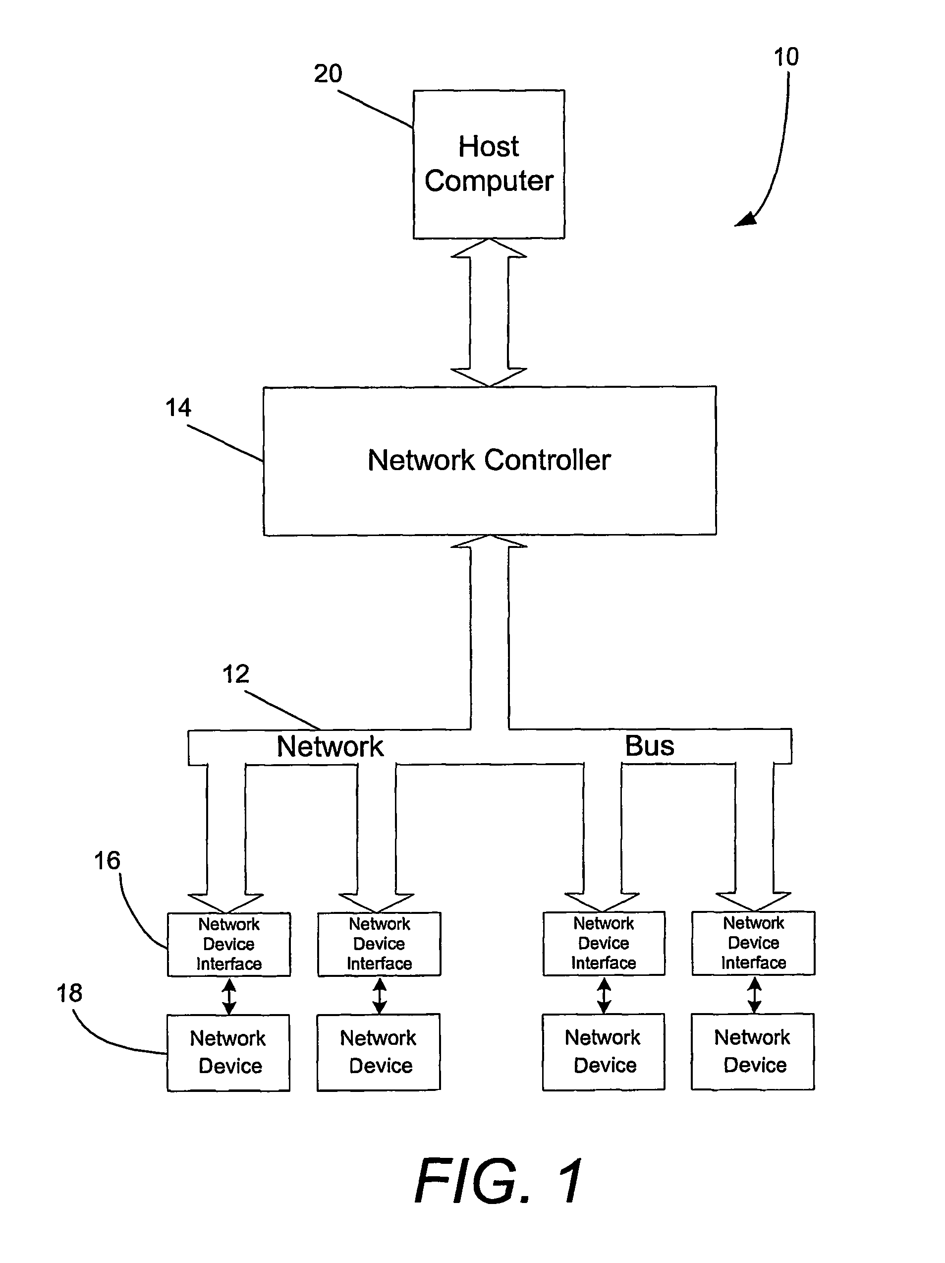
As systems have become more integrated and the communications requirements have been increased, the amount of dedicated wiring that would be required can quickly become excessively large, both in terms of the space required for the wiring and the cost of the wiring and the attendant installation.
Moreover, as the amount of dedicated wiring increased, the overall complexity of the system also generally increased as well as the likelihood that some portion of the wiring might be damaged or broken during or following installation.
Unfortunately, analog signals are susceptible to noise introduced into the signals during data transmission.
Given that many of the transmitted signals have a low amplitude to start with, this noise can corrupt the signal and decrease the signal to noise ratio to levels that cause loss of resolution in the signal.
Further, as many of these network devices are scattered some distance from the controller, the electrical lines connecting the network devices to the controller may be sufficiently long to cause signal degradation due to DC resistance in the wiring.
But, many conventional digital networks suffer from a variety of problems themselves.
For example, many existing digital networks operate according to complicated protocols which require each network device to have a relatively high level processor, thereby increasing the cost of the network devices.
This overhead can severely limit the number of data samples that can be transmitted on the bus.
These networks also have other problems.
For example, they generally do not support both acquisition and control, and they typically only support networks that extend over relatively short lengths.
Further, these networks typically have bulky network device interfaces, slow network data rates and / or a low network device count.
Additionally, many computer systems that include digital networks do not operate in a time-deterministic manner.
As such, these computer systems generally lack the capability to schedule a trigger command to the network components that repeats or is interpreted and executed with any precision timing.
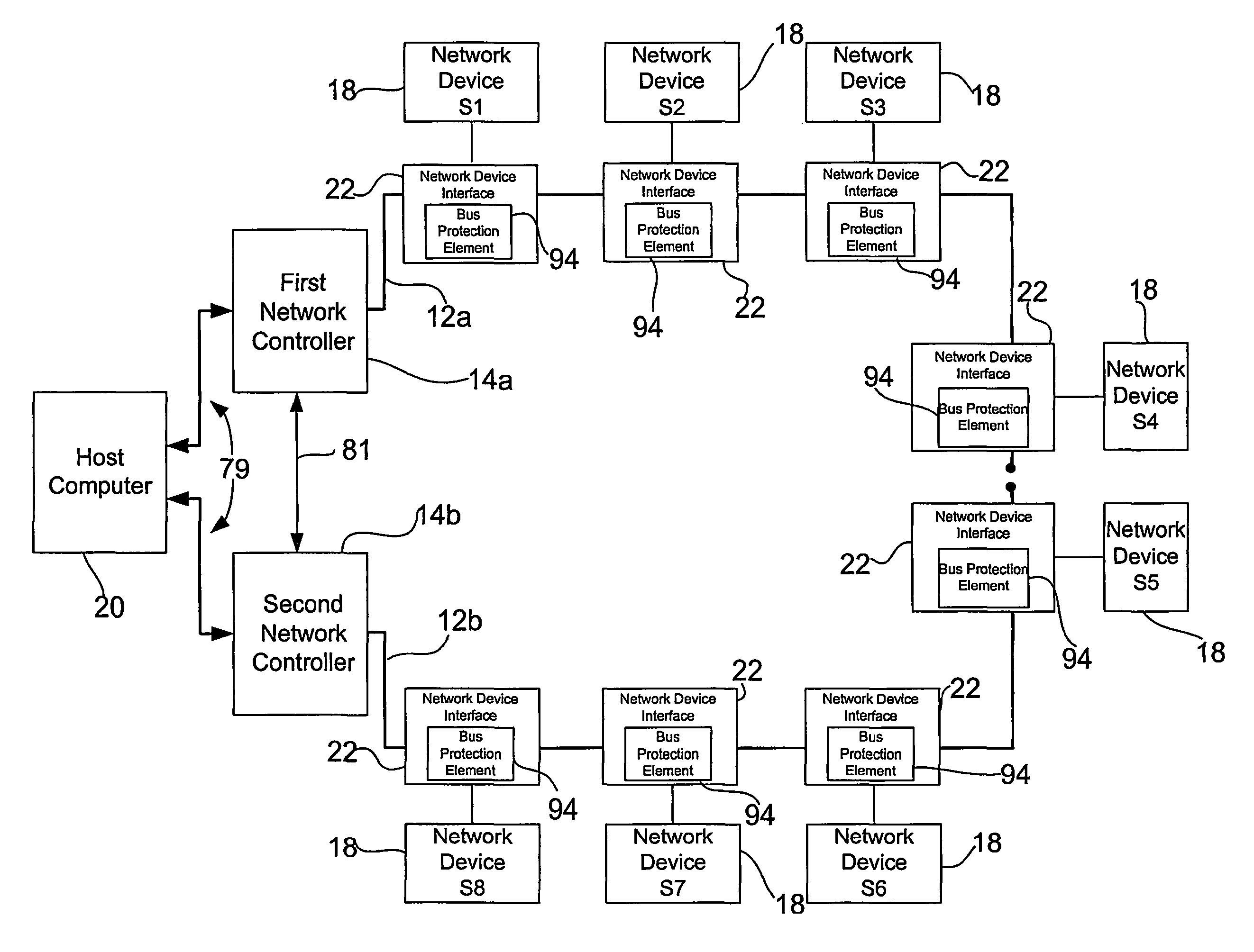
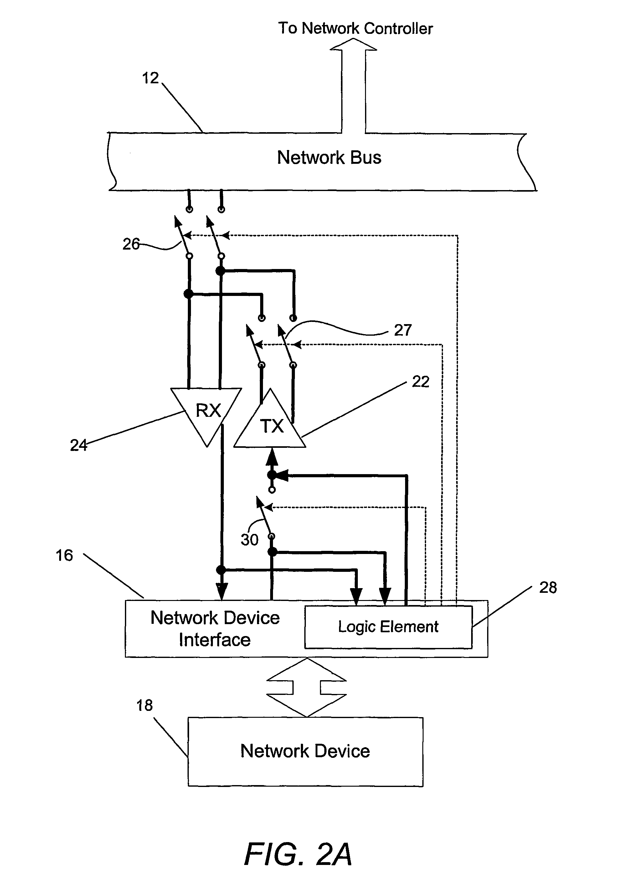
Regardless of the digital or analog nature of network, the network bus may be damaged during or following installation.
Due to accidents or other unforeseen circumstances, one or more of the wires may be broken, thereby creating an open circuit.
Thus, components on one side of the open circuit will be unable to communicate via the broken conductor with components on the other side of the open circuit.
Additionally, signals transmitted over the broken conductor will be reflected by the broken end of the conductor due to the characteristic impedance mismatch.
The reflected signals will then be returned along the conductor, thereby interfering, both constructively and destructively, with other signals being transmitted via the conductor.
While the components on one side of the open circuit may be able to communicate at relatively low data rates, such as ten kilobits per second, reflected signals will generally prevent effective communications between the components at higher data rates such as ten megabits per second or the like.
The destructive interference caused by the reflected signals caused by the open circuit will render the signals on the broken conductor more susceptible to noise, thereby further limiting effective communications.
Since a number of applications require that communications be conducted via the network bus at relatively high data transfer rates, the intentional slowing of the data over the network bus to reduce, if not negate, the deleterious impact of reflected signals may be inappropriate.
However, the physical repair of the network bus oftentimes requires that the network bus be removed from service for some period of time, which action may also be inappropriate for certain applications, such as time-sensitive applications or other applications that demand continuous monitoring or feedback.
A network bus may have other types of failures in addition to failures attributable to an open circuit.
In this instance, the network controller and the network devices will no longer be able to communicate via the pairs of conductors that are shorted.
In addition to short circuit and open circuit conditions on the network bus, a network device that is electrically connected to the network bus may fail and, as a result, may create problems for the network bus and for other network devices connected to the network bus.
In this regard, some failure modes of the network devices are self-limiting in that failure of a network device does not adversely impact continued communications of the other network devices over the network bus.
However, other failure modes of the network devices may create problems on the network bus and effectively prevent other network devices from communicating via the network bus.
As will be apparent, the process of identifying the network device that is babbling and thereafter removing the babbling network device from the network bus can be time-consuming, during which time the network bus will be unavailable for communications between the other network devices and the network controller.
Yet another type of failure of a network device that could cause the whole network to fail is that of a short circuit condition inside the network device that causes it to draw too much current.
If the network device draws more than the amount of current that can properly be supplied by the power supply in the network controller and power conductors of the network bus, the power voltage supplied to the other network devices will drop to levels that will cause them to be inoperable.
As will be apparent, the process of identifying the network device that is shorted and thereafter removing the shorted network device from the network bus can be time-consuming, during which time the network bus will be unavailable for communications between the other network devices and the network controller.
As described above in conjunction with the repair of a network bus having an open circuit condition, the removal of a network bus from service in order to repair a short circuit condition or to remove a network device that is babbling from the network bus will require that the network bus be out of service for some period of time and would therefore be inappropriate for certain applications including time-sensitive applications or other applications that demand continuous monitoring or feedback.

Method used


Image

  • System and method for maintaining proper termination and error-free communication in a network bus
  • System and method for maintaining proper termination and error-free communication in a network bus
  • System and method for maintaining proper termination and error-free communication in a network bus

Examples


Embodiment Construction

[0040]The present invention now will be described more fully hereinafter with reference to the accompanying drawings, in which preferred embodiments of the invention are shown. This invention may, however, be embodied in many different forms and should not be construed as limited to the embodiments set forth herein; rather, these embodiments are provided so that this disclosure will be thorough and complete, and will fully convey the scope of the invention to those skilled in the art. Like numbers refer to like elements throughout.

[0041]Referring now to FIG. 1, a system 10 that would benefit from the protection afforded by the present invention is depicted. While several embodiments of the system are illustrated and will be hereinafter described for purposes of example, other types of systems can readily employ the protection afforded by the present invention. Moreover, the system and method of the present invention will be primarily described in conjunction with automotive and aero...


PUM


Abstract

A system for maintaining proper termination and error-free communication in a network bus (12) including a power bus includes at least one network device (18), a network controller (14) and at least on bus protection element. The network devices (18) are electrically connected to and adapted to communicate via the network bus (12). The network controller (14), in turn, is electrically connected to the network bus (12) and is adapted to direct communications with the network devices (18) via the network bus (12). The network controller (14) is also adapted to provide power signals to the network devices (18) via the power bus of the network bus (12). The network controller (14) and/or the bus protection elements can monitor signals on the network bus (12). And based upon the network controller (14) and/or bus protection elements identifying a predefined number of improper signals, the bus protection elements can selectively connect and disconnect respective network devices (18) to and from the network.

Description

FIELD OF THE INVENTION[0001]The present invention relates generally to systems and methods for reliably communicating over a network bus and, more particularly, to systems and methods for maintaining the proper termination and error-free communication in a network bus in the event of various types of bus failures including a short circuit condition, an open circuit condition or a network device that improperly occupies the network bus with meaningless data.BACKGROUND OF THE INVENTION[0002]As systems, such as multimedia entertainment, communications, process control systems and diagnostic systems utilized by the automotive and aerospace industries, become more complex, a need arises for additional devices to communicate, either with each other or with a central controller or the like. Historically, these systems included dedicated wiring extending between the various devices in order to support communications therebetween. As systems have become more integrated and the communications...

Claims


Application Information

Patent Timeline
Patent Type & Authority Patents(United States)
IPC IPC(8): G06F15/177G06F3/00G06F13/00G06F13/40H04B1/74H04L12/12H04L12/28H04L12/40H04L12/403H04L69/40
CPCG06F13/4068H04L69/40H04L12/12H04L12/40032H04L12/40045H04L12/40169H04L12/403H04L43/0823H04L43/16H04B1/74H04L43/0811H04L43/0817H04L43/103H04L2012/40267Y02B60/34Y02D30/50Y04S40/00G06F13/38
Inventor KONZ, DANIEL W.ELLERBROCK, PHILIP J.
Owner THE BOEING CO
Why Eureka
Try Eureka