Snow removing machine

a self-propelled, snow removing machine technology, applied in snow cleaning, way cleaning, construction, etc., can solve the problems of difficult to achieve the desired turning radius, large load on the human operator, etc., to improve the turning performance of the snow removing machine, smooth switch, and high maneuverability

Inactive Publication Date: 2009-09-01
HONDA MOTOR CO LTD
View PDF23 Cites 12 Cited by
  • Summary
  • Abstract
  • Description
  • Claims
  • Application Information

AI Technical Summary

Benefits of technology

[0010]In view of the foregoing prior art problems, it is an object of the present invention to provide a technique which can effectively improve turning performance of a snow removing apparatus equipped with left and right running devices and an auger.
[0013]With the “inner” side edge of the auger housing caused to contact the ground surface, there is produced a new traveling resistance against the inner side edge, and thus, the machine can turn about the portion of the ground-contacting inner side edge as a pivot center.
[0014]Thus, as the human operator operates the turning operator, not only one of the running devices, located inwardly of the other running device as viewed in the turning direction, can be slowed down but also the auger housing can be rolled in such a manner as to cause the inner side edge to contact the ground surface, which can thereby enhance the turning performance of the snow removing machine. Therefore, by the human operator operating the turning operator, the snow removing machine can be smoothly switched from straight travel to turning travel. As a result, the snow removing machine of the invention can be highly maneuverable and usable with ease and, therefore, can efficiently perform snow removal work even in small working areas.
[0015]The snow removing machine of the invention may further comprise left and right operating handles extending from a rear portion of the running-device frame, and the turning operator may comprise left and right turning operators, such as left and right operation levers operable by the hands of a human operator holding the left and right operating handles, or left and right push-button switches provided between the left and right operating handles at positions within ranges operable by the hands of the human operator holding the left and right operating handles. Thus, the human operator can also operate the left and right turning operator members with the same hands holding the operating handles to manipulate the snow removing machine. Therefore, it is not necessary to rehold or release or let go of any of the left and right operating handles each time the human operator performs operation for turning the snow removing machine to the left or right. As a consequence, the present invention can enhance the operability of the snow removing machine and allows the human operator to turn the machine with ease. With such an enhanced turning operability and turning capability of the snow removing machine, the overall performance of the machine can be significantly improved. Further, because only the operation levers or push buttons have to be provided near the left and right operating handles for purposes of turning the machine, the present invention can reduce the number of components necessary to implement the turning operator and thereby simplify the construction of the turning operator.
[0016]The snow removing machine may further comprise an auger-housing-posture manipulating lever for operating the rolling drive mechanism to roll the auger housing in accordance with a snow surface during snow removal work using the auger. In this case, the auger-housing-posture manipulating lever may be caused to also function as the turning operator. Thus, it is possible to dispense with the separate or dedicated turning operator. Even though the snow removing machine has no dedicated turning operator, the human operator can use the auger-housing-posture manipulating lever to readily perform operation for turning the machine. Thus, the present invention can achieve an enhanced turning operability, sufficient turning performance and hence enhanced overall performance of the snow removing machine. Since the number of necessary operator members can be minimized, such inventive arrangements can be suitably applicable to snow removing machines that have to be small in size or have other spatial limitations. Further, because the number of necessary component parts can be reduced, it is possible to reduce the manufacturing cost of the snow removing machine.

Problems solved by technology

Where the auger height is adjusted through manual input operation by a human operator, the input operation tends to be a great load on the human operator.
Thus, it tends to be difficult to attain a desired turning radius when the human operator performs operation for switching from the straight travel to the turning travel, and further improvements must be made in order to allow the snow removing machine 200 to smoothly switch from the straight travel to the turning travel.

Method used


Image

  • Snow removing machine
  • Snow removing machine
  • Snow removing machine

Examples


first embodiment

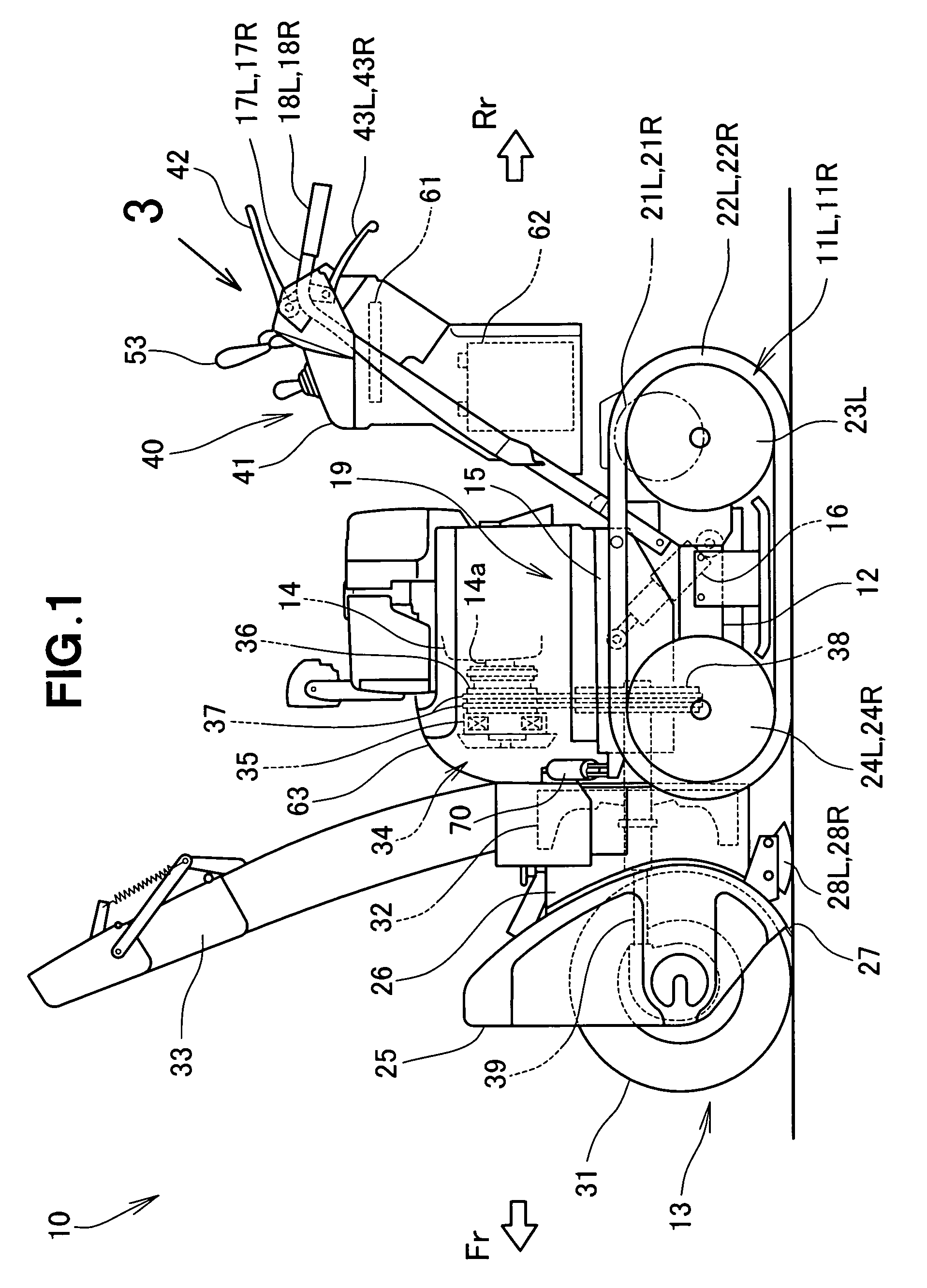
[0039]FIG. 1 is a side view showing a snow removing machine in accordance with the present invention, the snow removing machine 10 of FIG. 1 is a self-propelled vehicle, in which a snow removal work section 13 and an engine 14 for driving the snow removal work section 13 are mounted on a vehicle body frame (second frame) 15, and in which the vehicle body frame 15 is vertically pivotably connected at its rear end portion to a running-device frame (first frame) 12 having left and right running (transporting) devices 11L and 11R mounted thereon. Further, in the snow removing machine 10, a front portion of the vehicle body frame 15 can be moved in an upward / downward direction (i.e., vertically pivoted) via an auger housing elevator mechanism 16. Left and right operating handles 17L and 17R extend upwardly and rearwardly from a rear portion of the running-device frame 12, and grips 18L and 18R are fixed to the respective digital ends of the left and right operating handles 17L and 17R.

[0...

second embodiment

[0152]The following paragraphs describe a modification of the above-described snow removing machine 10 (i.e., snow removing machine according the present invention), with primary reference to FIGS. 13-19.

[0153]The snow removing machine 10 according to the second embodiment is characterized in that the auger-housing-posture manipulating lever itself 52A is equipped with the functions of the left and right turning operator members (left and right turning operation levers 43L and 43R, or left and right turning operation switches 47L and 47R. Thus, in the second embodiment, there is no need to provide the left and right turning operation levers 43L and 43R, or left and right turning operation switches 47L and 47R employed in the above-described first embodiment

[0154]The other arrangements of the second embodiment are similar to those shown in FIGS. 1-5 and will not be described here to avoid unnecessary duplication.

[0155]FIG. 13 shows the modified auger-housing-posture manipulating leve...


PUM


Abstract

A snow removing machine has a frame, a pair of transporting devices mounted on the frame for transporting the snow removing machine on a ground surface, an auger housing having an auger housed therein and mounted on the frame for undergoing rolling movement, a rolling drive mechanism coupled to the auger housing for providing rolling movement of the auger housing relative to the frame, and a turning mechanism operable to turn the snow removing machine in a preselected direction. In response to operation of the turning mechanism, a control section performs a control operation to drive the transporting devices to thereby turn the snow removing machine in the preselected direction and performs a control operation of the rolling drive mechanism to provide rolling movement of the auger housing relative to the frame.

Description

FIELD OF THE INVENTION[0001]The present invention relates to self-propelled snow removing machines including left and right running devices and an auger.BACKGROUND OF THE INVENTION.[0002]In many snow removing machines provided with an auger, there is employed a technique in accordance with which the auger is varied in height in accordance with conditions of snow removal work. When the snow removing machine should travel, it can do so more efficiently with the lower end surface of the auger positioned higher. When, on the other hand, the snow removing machine should remove snow, it can do so more efficiently with the lower surface of the auger positioned lower. Further, in many cases, the height of the auger is adjusted in accordance with road surface irregularity or unevenness. Where the auger height is adjusted through manual input operation by a human operator, the input operation tends to be a great load on the human operator.[0003]Auger-type snow removing machines, constructed t...

Claims


Application Information

Patent Timeline
Patent Type & Authority Patents(United States)
IPC IPC(8): E01H5/04
CPCE01H5/04
Inventor MIZOROKE, TSUTOMUKAWAKAMI, TOSHIAKIONO, NAOTOSHI
Owner HONDA MOTOR CO LTD
Why Eureka
Try Eureka