Wiper bearing

a bearing and wrist technology, applied in the direction of bearing unit rigid support, vehicle maintenance, vehicle cleaning, etc., can solve the problem of especially compact construction, and achieve the effect of simple tool structure, good positive engagement, and simple tool structur

Inactive Publication Date: 2009-09-01
ROBERT BOSCH GMBH
View PDF28 Cites 34 Cited by
  • Summary
  • Abstract
  • Description
  • Claims
  • Application Information

AI Technical Summary

Benefits of technology

[0004]In the case of a wiper bearing in accordance with the invention, it is proposed that an annular element that is arranged in a coaxial manner on the journal be provided outside a journal that is provided to receive a tubular plate. The journal is permanently connected to an outer tube of the wiper bearing forming the bearing housing or to an inner tube arranged in a concentric manner in relation thereto. Due to a positively engaged connection of the tubular plate with the journal, forces are transferred from the bearing housing to the journal including torsional forces. The journal henceforth assumes mainly tensile forces, compressive forces and torsional forces. The annular element and its connecting braces assume bending moments and bending forces. The journal is mechanically stressed less and more uniformly as a whole. The annular element can essentially assume bending forces, which act in a plane, which is formed of a bearing axis and the journal. The tubular plate is supported by the annular element and the journal is relieved correspondingly. Only slight bending loads occur on the journal itself. It is also possible to provide two coaxially arranged annular elements. In this case, the outer annular element has very good stability and eases the connection of the tubular plate with the journal. The construction is especially compact when the journal is fastened to the inner tube. The initiation of force in this case takes place on both the inner tube as well as on the outer tube.
[0005]Because of the low stress, a transitional geometry between the journal and its bearing point on the bearing housing can be designed simply with a shortened distance between a connecting area between the journal and the tubular plate and the bearing area of the journal on the inner tube or outer tube of the bearing housing. The wiper bearing, in particular a wiper bearing made of plastic, can be designed to be shorter and more compact than previous plastic wiper bearings in which attention had to be paid to a long and harmonic transitional area in order to reduce any mechanical tension spikes occurring there. Because of the compact design of the wiper bearing, the tubular plate can be brought closer to the bearing area of the wiper axis, thereby resulting in a more rigid overall system. Because of the uniform mechanical stress of the bearing housing, it can be designed in a uniformly thin-walled manner, which is especially advantageous for a wiper bearing design of plastic in order to avoid bubbles forming in the plastic during manufacturing. In addition, a shorter cooling and cycle time during manufacturing is made possible. In connection with the reduced dead weight, the wiper bearing with the annular element can be cost-effectively manufactured and mounted. The tubular plate can be designed with a small cross section, which signifies a reduction in weight and a lower requirement for construction space. Because of elastic deformation, for example in the case of a lock-up, wiper supports with a smaller cross section of the tubular plate relieve all components of the wiper system, even the wiper lever, thereby making possible additional cost savings since these components can be designed more simply.
[0006]Because of the arrangement of the annular element and the improved support of the tubular plate in the bearing area, less movement occurs when operating the wiper system and even in the case of high loads the connecting point will not fail. The alignment of the wiper shaft remains practically unchanged so that, according to the design, the adjustment angle of the wiper blade to the vehicle window is retained, thereby guaranteeing good wiping quality.

Problems solved by technology

The construction is especially compact when the journal is fastened to the inner tube.

Method used


Image

  • Wiper bearing
  • Wiper bearing
  • Wiper bearing

Examples


Embodiment Construction

[0029]The invention is particularly suitable for wiper bearings made of plastic. In general, the same reference numbers are used in the figures for the same parts.

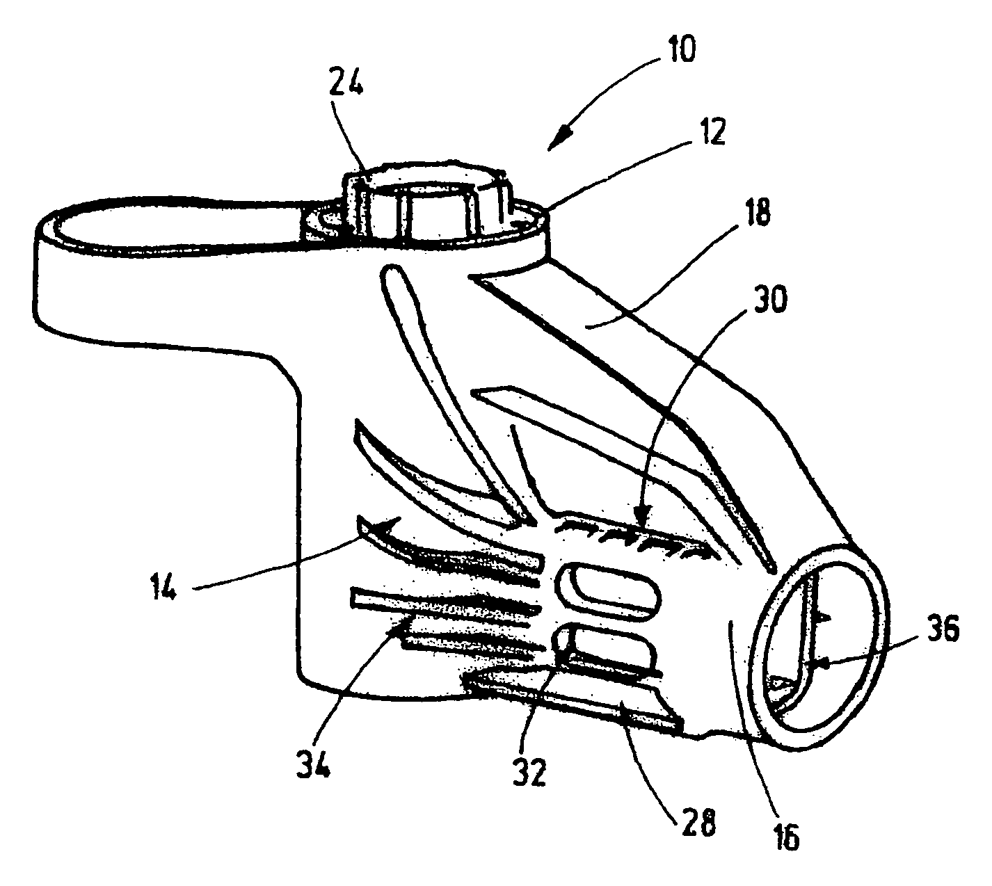
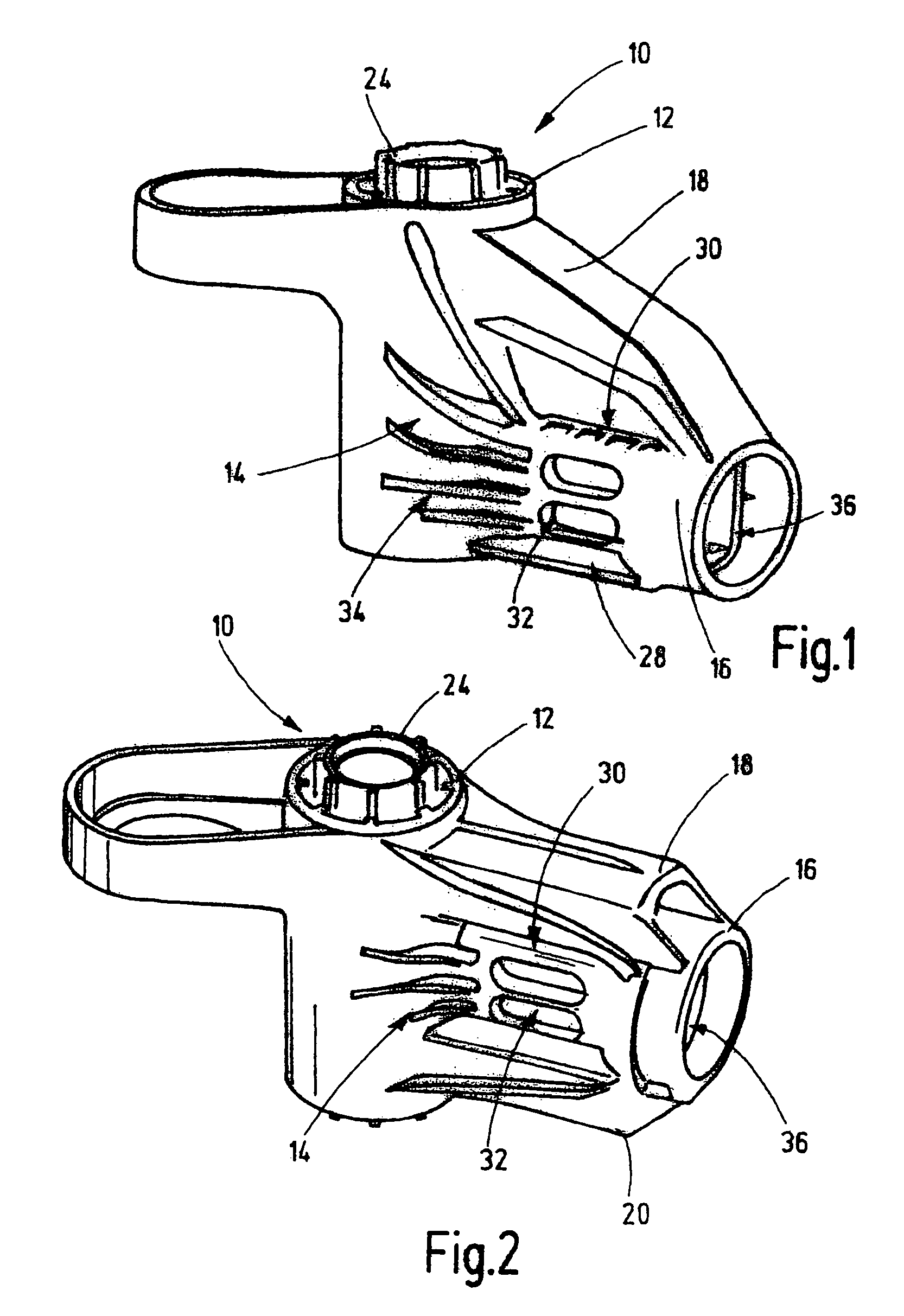
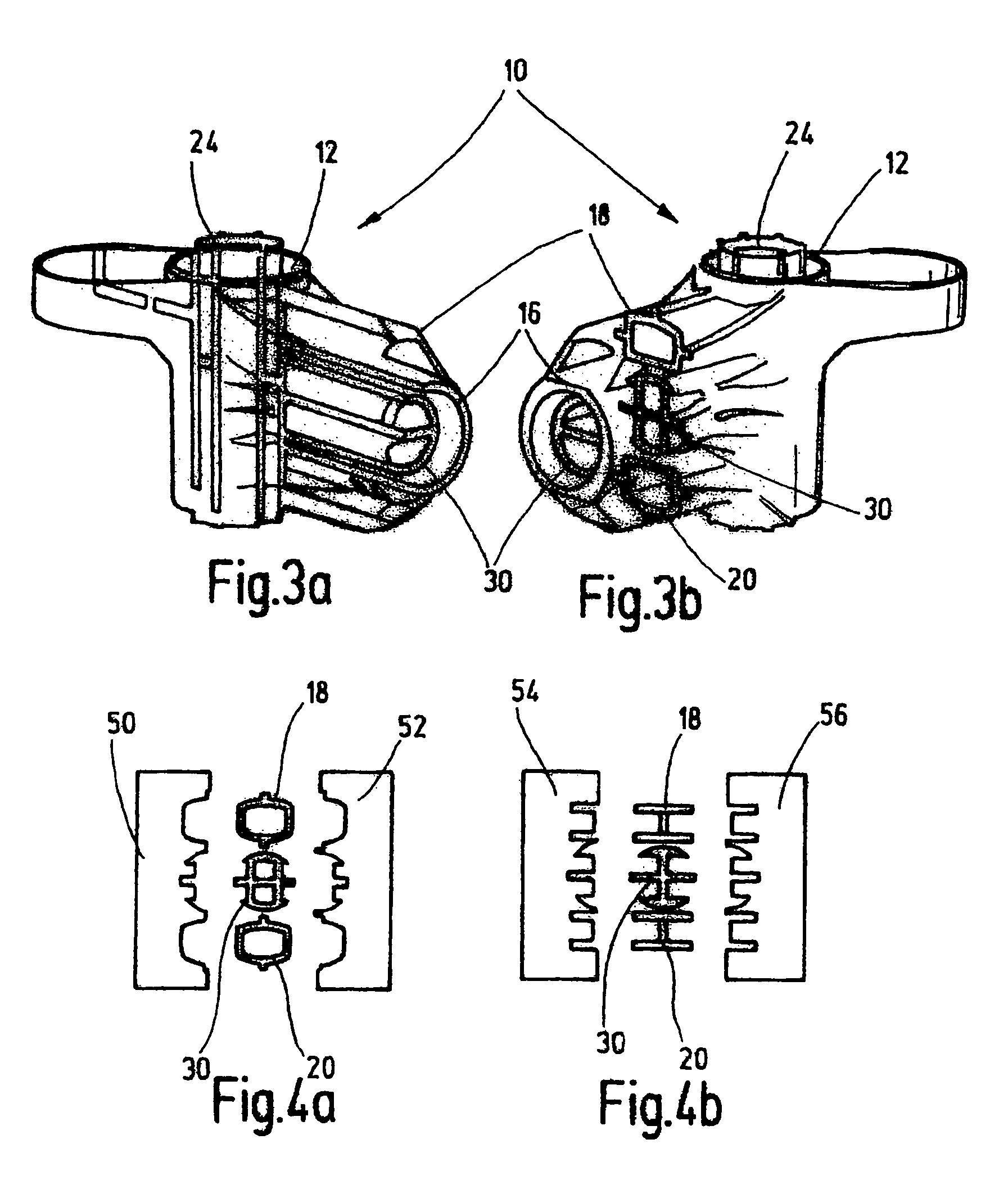
[0030]FIG. 1 shows a wiper bearing 10 for a windshield wiper system with a bearing housing 12 and a journal 30 arranged on a bearing area 14 on a bearing housing 12 and a short annular element 16. The bearing housing 12 formed by an outer tube concentrically surrounds an inner tube 24. The short annular element 16 is arranged coaxially outside the journal 30 in the area of its front side 36. The journal 30 and the annular element 16 are arranged off-center with respect to an axial extension of the bearing housing 12.

[0031]The annular element 16 is fastened on the bearing housing 12 with an upper brace 18 and a lower brace 20, through which the journal 30 is accessible from the outside at least in a connecting area 32. A tubular plate (not shown) will subsequently be connected to the journal 30 in this connecting area 32. T...


PUM


Abstract

The invention relates to a wiper bearing for a windshield wiper system comprising a bearing housing (12) provided with an outer tube forming the bearing housing (12) and an inner tube (24) arranged in a concentric manner in relation thereto and a journal (30) arranged on a bearing area (14) on the bearing housing (12) for receiving a tubular plate (40). It is proposed that an annular element (16), which is arranged in a coaxial manner on the journal (30), be provided outside the journal (30) in the region of the front side thereof (36).

Description

BACKGROUND OF THE INVENTION[0001]The invention starts with a wiper bearing.[0002]A wiper bearing housing is used to support a wiper shaft and to position a wiper axis as well as fastening receptacles for assembly in a vehicle. High forces and moments occur above all in the transition area between the wiper bearing housing and the tubular plate, particularly in the case of snow load or cases of lock-up.[0003]A wiper system is known from DE 199 25 292 A1 in which the tubular plate in the transition area has an enlarged cross section, which reduces the specific load in the critical transition area and increases flexural strength and resistance to torsion.SUMMARY OF THE INVENTION[0004]In the case of a wiper bearing in accordance with the invention, it is proposed that an annular element that is arranged in a coaxial manner on the journal be provided outside a journal that is provided to receive a tubular plate. The journal is permanently connected to an outer tube of the wiper bearing f...

Claims


Application Information

Patent Timeline
Patent Type & Authority Patents(United States)
IPC IPC(8): F16C33/02F16C17/02B60S1/04
CPCB60S1/0425B60S1/04
Inventor ZIMMER, JOACHIM
Owner ROBERT BOSCH GMBH
Why Eureka
Try Eureka