High performance adaptive optics with a reconstructed coherent wave front

a coherent wave front and adaptive optics technology, applied in the field of adaptive optics, can solve problems such as the inability of systems to operate at higher frame rates

Active Publication Date: 2009-09-01
LOCKHEED MARTIN CORP
View PDF3 Cites 5 Cited by
  • Summary
  • Abstract
  • Description
  • Claims
  • Application Information

AI Technical Summary

Benefits of technology

[0005]The present invention solves the foregoing problems by providing high performance adaptive optics systems and methods which can correct phase aberrations at very high frame rates, making them suitable for use in dynamically scintillating conditions. A coherent hologram is formed by interfering an incoming aberrated beam with a tilted self reference beam. Th

Problems solved by technology

Such systems are incapable of operating at higher frame rates, bec

Method used


Image

  • High performance adaptive optics with a reconstructed coherent wave front
  • High performance adaptive optics with a reconstructed coherent wave front
  • High performance adaptive optics with a reconstructed coherent wave front

Examples


Embodiment Construction

[0029]In the following detailed description, numerous specific details are set forth to provide a full understanding of the present invention. It will be apparent, however, to one ordinarily skilled in the art that the present invention may be practiced without some of these specific details. In other instances, well-known structures and techniques have not been shown in detail to avoid unnecessarily obscuring the present invention.

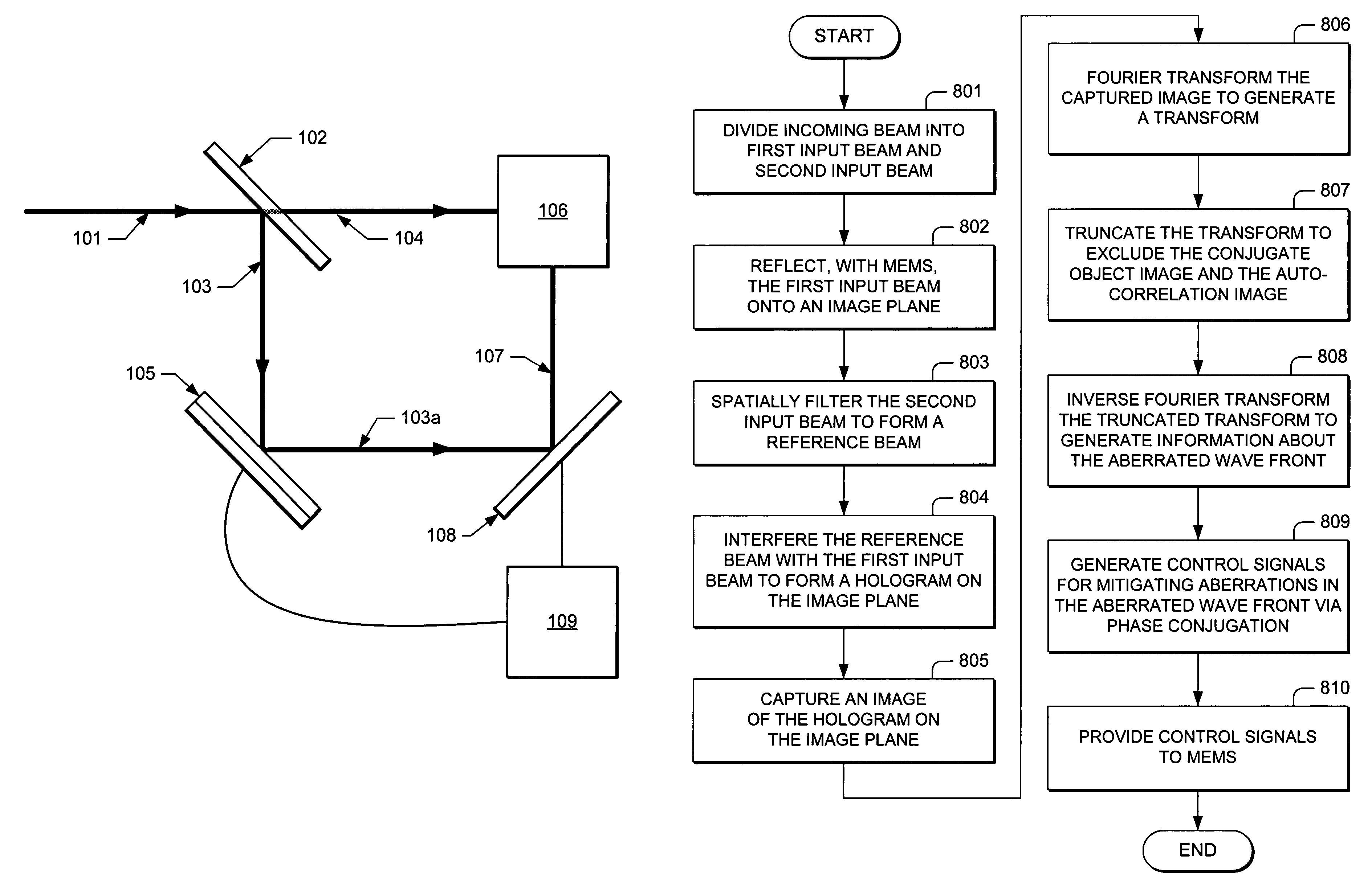
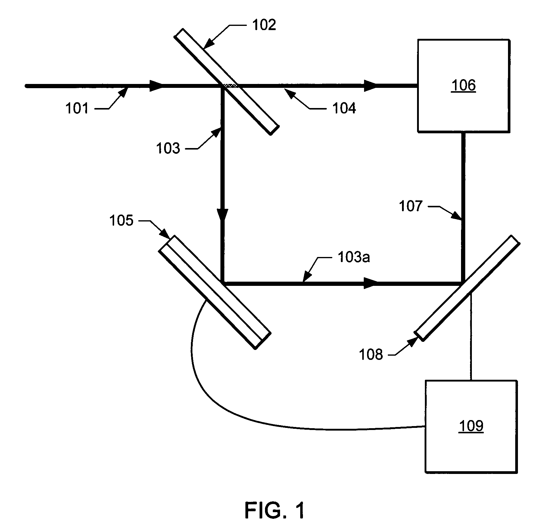
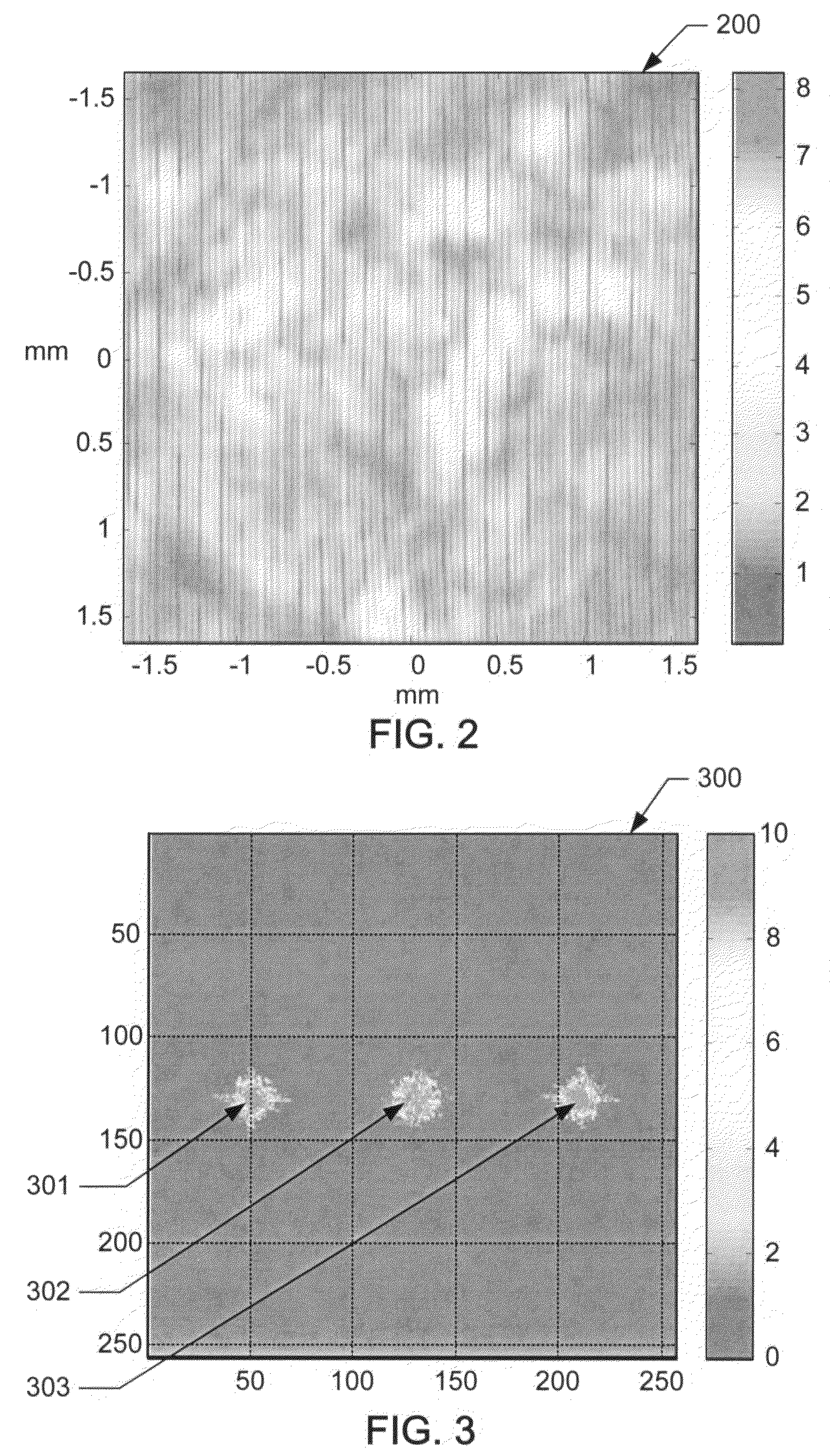
[0030]FIG. 1 illustrates an adaptive optics system according to one embodiment of the present invention. The adaptive optics system includes a beamsplitter 102, which splits an incoming beam 101 with an aberrated wave front into two identical beams 103 and 104. Beam 103 is reflected off of MEMS 105 onto an image plane of imaging device 108. Beam 104 is spatially filtered by a self-reference wave front generator (“SRWG”) 106 to produce a reference beam 107 with a flat phase. Reference beam 107 is directed by SRWG 106 onto the image plane, where it is inter...


PUM


Abstract

An adaptive optics system comprises a beamsplitter configured to divide an incoming beam with an aberrated wave front into a first input beam and a second input beam, a microelectromechanical system configured to reflect the first input beam onto an image plane, and a self-reference wave front generator configured to spatially filter the second input beam to form a reference beam, and to interfere the reference beam with the first input beam on the image plane to form a hologram. The system further comprises an imaging device configured to capture an image of the hologram on the image plane, and one or more processors. The one or more processors are configured to perform the steps of Fourier transforming the captured image to generate a transform including a first object image, a conjugate object image, and an auto-correlation image, truncating the transform to exclude the conjugate object image and the auto-correlation image, inverse Fourier transforming the truncated transform to generate amplitude and phase information about the aberrated wave front, generating control signals for mitigating aberrations in the aberrated wave front via phase conjugation based on the amplitude and phase information, and providing the control signals to the microelectromechanical system.

Description

CROSS-REFERENCE TO RELATED APPLICATION[0001]The present application claims the benefit of priority under 35 U.S.C. § 119 from U.S. Provisional Patent Application Ser. No. 60 / 800,862 entitled “HIGH PERFORMANCE ADAPTIVE OPTICS FOR RECONSTRUCTING A COHERENT WAVE FRONT,” filed on May 17, 2006, the disclosure of which is hereby incorporated by reference in its entirety for all purposes.STATEMENT REGARDING FEDERALLY SPONSORED RESEARCH OR DEVELOPMENT[0002]Not applicable.FIELD OF THE INVENTION[0003]The present invention generally relates to adaptive optics and, in particular, relates to high performance adaptive optics systems and methods.BACKGROUND OF THE INVENTION[0004]Adaptive optics (“AO”) are used to control deformable mirrors to compensate for phase aberrations introduced, for example, by the turbulence in the Earth's atmosphere or by the optical elements between a distant object and its local sensor. Various low speed AO systems use a Shack Hartmann sensor and a least square reconstr...

Claims


Application Information

Patent Timeline
IPC IPC(8): G03H1/16
CPCG02B26/06G03H1/0402G03H1/0443G03H2001/0445Y10S359/90
Inventor WILLIAMS, SAMUEL G.PHAM, ICH V.
Owner LOCKHEED MARTIN CORP
Why Eureka
Try Eureka