Studded plate with fold line

a technology of plate and fold line, applied in the direction of treads, building components, protective foundations, etc., can solve the problems of difficult detection, inability to place concrete directly on the floor, and inability to place concrete floor coverings such as wooden floors, so as to reduce the risk of capillary action in a simple and sure manner

Inactive Publication Date: 2009-09-08
ISOLA GESELLSCHAFT M B H
View PDF84 Cites 68 Cited by
  • Summary
  • Abstract
  • Description
  • Claims
  • Application Information

AI Technical Summary

Benefits of technology

[0015]The present invention concerns a studded plate wherein at least one edge in the longitudinal direction of the plate has a fold line which maintains airflow even when the plate is folded at 90° along the edge. The described studded plate thereby secures venting and equalization of the water vapour pressure across the floor, as well as reducing the risk of capillary action.
[0017]The main advantage with this system is that a whole room may be covered with one type of plate without the need for other specialty plates and parts other than a jointing tape.

Problems solved by technology

Floor coverings such as wooden floors can therefore not be placed directly on the concrete.
The floor may also be affected by rising damp.
Initially, all concrete floors contain residual moisture and the above problem therefore concerns cellars, basement floors, slab on ground floors and floor between different storeys of different types of concrete, including for example floors made of light expanded clay aggregate concrete and lightweight concrete.
The moisture in the concrete is often invisible and difficult to detect.
This results in an unawareness of the risks such as rot, moisture damage etc.
Without an effective damp proof membrane with sufficient performance characteristics, moisture from the concrete will for example attack wood materials from underneath.
The same problem also concerns tiled floors wherein the filled joints will allow passage of moisture.
The result is damaged floors with cracks, mould and rot.
In addition, hazardous mould spores, bad smell and a poor in-door environment may result.
However, it is a problem with the above mentioned solution that a plate placed on the floor should be turned up against the wall of the room, in order to guide the humid air out of the air gap.
The problem with this solution is that all the above mentioned plates thereby obtain a folding crease which either inhibits the transport of humid air or for example the plate comes in direct contact with the adhesive used against the floor thereby blocking the air gap.
However, there is always a risk that plates on the floor are pushed towards the wall and will remain in contact with the wall, or that adhesive is pressed into the junction between the floor and the wall, thereby blocking the venting.

Method used


Image

  • Studded plate with fold line
  • Studded plate with fold line
  • Studded plate with fold line

Examples


first embodiment

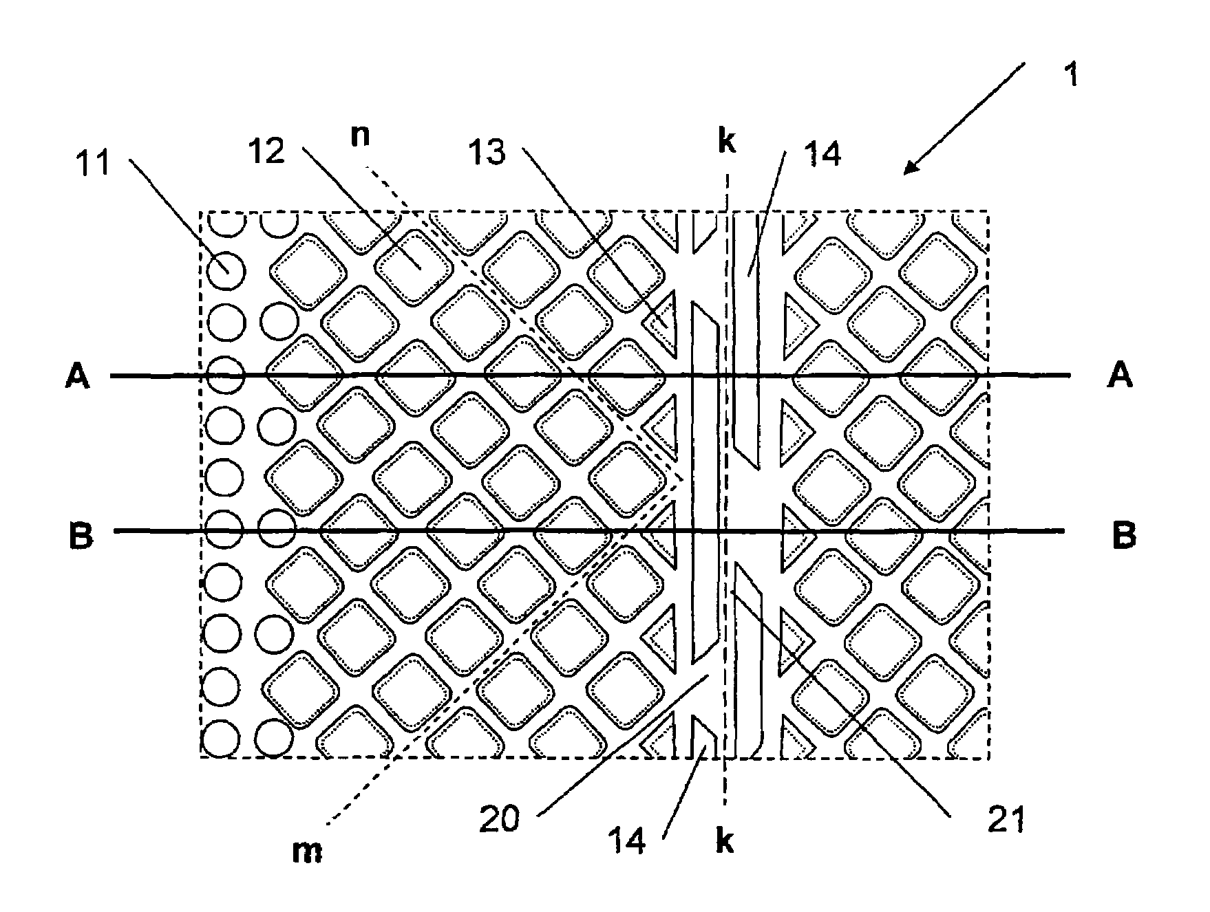
[0040]the invention is shown in FIG. 1, which is a part of a studded plate according to the invention. The plate has a longitudinal direction L and normally such sheets are rolled up in lengths of 20 meters. The plate has a transverse direction W, and the width of a sheet is normally about 1 or 2 meters. The height of the studs in this example is constant at about 3 millimeters, but may be smaller or larger or possibly of varying height.

[0041]In the longitudinal direction, the plate is divided in areas of different widths, comprising different types of studs 11, 12, 13 and 14 of different shapes and sizes when following the line a-b. The width of the different areas may vary and the line c-d designates an unidentified width. The line e-f marks an incomplete longitudinal edge as the plate may have different widths, either with the same type of studs, or other studs as shown on other parts of the plate in FIG. 1.

[0042]As may be seen from FIG. 1, an edge area of round small studs 11 is...

second embodiment

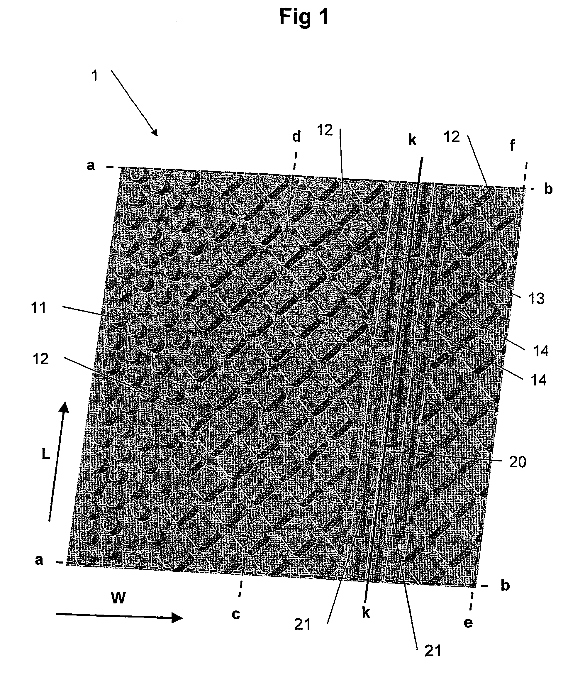
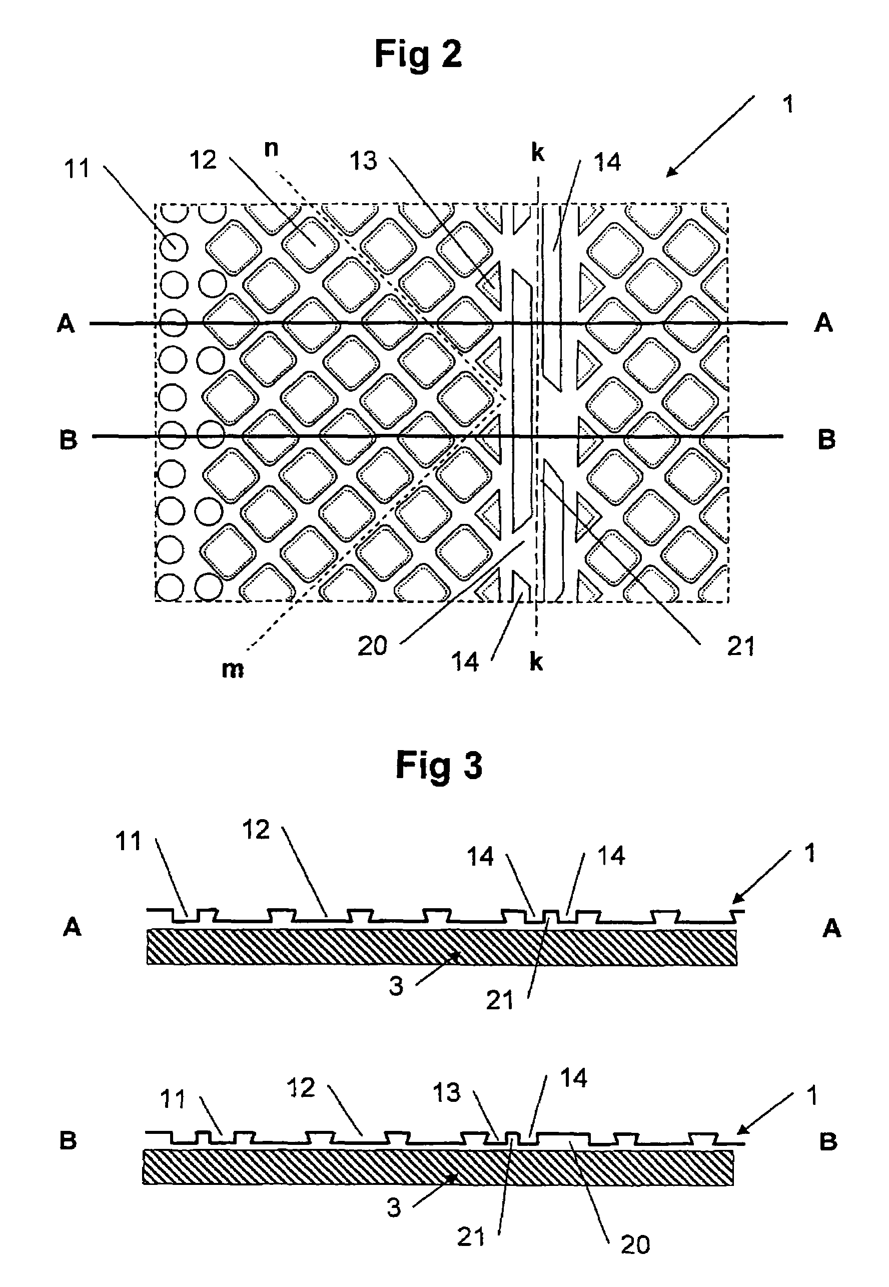
[0048]In order to better understand the shape of the studs, a similar second embodiment of a studded plate 1 is shown in FIG. 2, viewed from the bottom side with two marked sectional lines A-A and B-B. In FIG. 3 the profiles of cross sections A-A and B-B are represented with the plate placed against a substrate 3.

[0049]In order to fasten the studded plate to the substrate, it is an advantage, as mentioned initially, to use a fabric or a grid 2 as shown in FIG. 4 which may be applied to the studded plate in advance. The top of the studs 11, 12, 13 and 14 in FIG. 1 are for example provided with a fabric 2 in FIG. 4 of a suitable material by adhesive or lamination. This fabric 2 may then be used for fixing the plate to the substrate, such as a concrete floor or a wall, either permanently or temporarily. In FIG. 5 the profiles of the cross sections C-C and D-D are respectively reproduced when the plate 1 with fabric 2 is placed against a floor 3. As may be seen from the FIG. 5, the offs...

third embodiment

[0052]FIG. 8 shows a plate according to the invention comprising a fold line. In this embodiment the main areas comprise two types of studs, such as circular studs 112 and propeller shaped studs 110, both of which have undercuts, although somewhat offset. The fold line is made up of a central longitudinal row of oblong propeller shaped studs 114, and one row on each side, comprising oblong studs 113. As in the embodiments described earlier, this arrangement also secures a continuous air gap when the plate is folded in 90° along the line k-k which is the centre line of the folding crease. A continuous air gap is secured through the combination of channels 120 generally in the transverse direction and channels 121 generally in the longitudinal direction. The staggering of the studs in the three rows of the fold line will also prevent an optional fabric 2 on the bottom side of the plate in blocking the channels.


PUM

PropertyMeasurementUnit
lengthaaaaaaaaaa
widthaaaaaaaaaa
widthaaaaaaaaaa

Abstract

The present invention concerns a studded plate (1), comprising a first longitudinal edge (60) and a second longitudinal edge (61) between which edges are arranged a main area (90) in the longitudinal direction of the plate (1) comprising a first type of studs (12), characterized in that the main area (90) comprises at least one sub area (100), in the longitudinal direction of the plate (1), comprising at least one first row of a second type of studs (14, 114, 214) which have an oblong shape in the longitudinal direction of the plate (1) and at least one adjacent longitudinal row of a similar stud (14) and / or a third type of studs (13, 113, 213) comprising a longitudinal adjacent border to the first row of studs (12), wherein studs (14) in the first row are offset in the longitudinal direction in relation to the studs in the adjacent row(s).

Description

RELATED APPLICATION[0001]This application claims the benefit of priority from Norwegian Patent Application No. NO 20041545, filed on Apr. 15, 2004, in the Norwegian Patent Office, the disclosure of which is hereby incorporated herein by reference in its entirety.AREA OF THE INVENTION[0002]The present invention concerns a studded plate, such as a plate of a film like material, for use as a support against floors, walls, ceilings and roofs, and especially as a support for flooring on concrete floors with tiles, floor covering or wooden floors. The invention also concerns the use of the studded plate and a method of placement of the plate.TECHNICAL BACKGROUND[0003]Many different types of studded plates which may be used as supporting plates are known. They may be used as ordinary supporting plates, drainage plates, decoupling plates, or plaster plates for plastering or support for adhesive for tiles for example when flooring with ceramic tiles.[0004]All concrete floors resting on the g...

Claims


Application Information

Patent Timeline
Patent Type & Authority Patents(United States)
IPC IPC(8): B32B3/00E02B11/00E02D19/00B29C59/02E01C13/02E02B3/12E02D31/02E04B1/66E04D13/04E04F13/04E04F15/02E04F15/18
CPCE04F13/04E04F15/02E04F15/18Y10T428/24612Y10T428/24942Y10T428/24479E04F15/185E04F15/188E04F15/182
Inventor JULTON, SVEIN
Owner ISOLA GESELLSCHAFT M B H
Why Eureka
Try Eureka