
High speed data link with transmitter equalization and receiver equalization

a high-speed data and equalization technology, applied in the field of high-speed data links, to achieve the effect of improving the bit error rate (ber)

Active Publication Date: 2009-09-08
AVAGO TECH INT SALES PTE LTD
View PDF10 Cites 33 Cited by
  • Summary
  • Abstract
  • Description
  • Claims
  • Application Information

AI Technical Summary

Benefits of technology

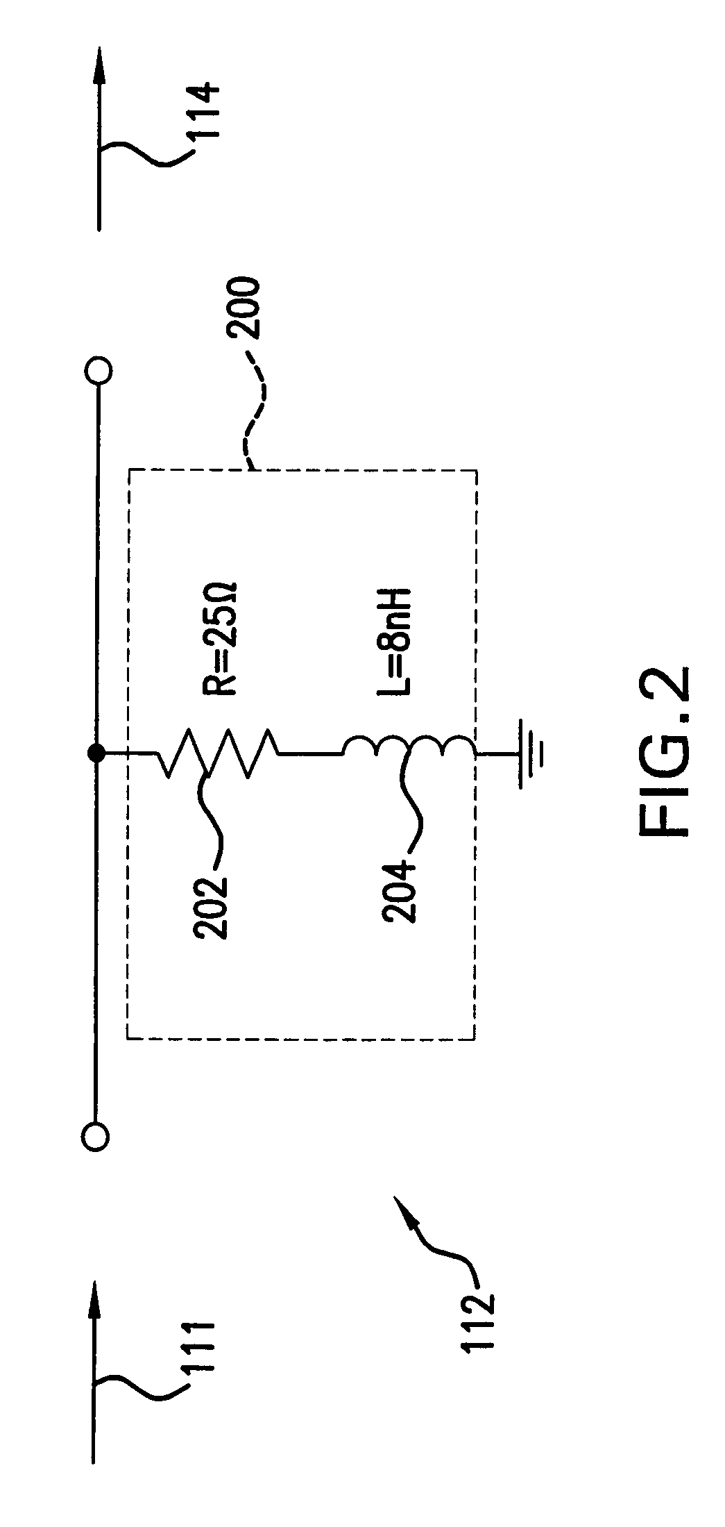
[0009]A high speed data link includes a transmitter equalization circuit and a (passive) receiver equalization circuit to compensate for frequency distortion of the data link. In one embodiment, the transmitter equalization circuit is a de-emphasis circuit. The transmitter de-emphasis circuit pre-distorts an input signal to compensate for at least some of the frequency distortion in the data that is caused by the transmission line in the data link. The (passive) equalization circuit incorporated in the Receiver further compensates for the frequency distortion at the output of the transmission line to flatten the amplitude response of the output signal, and thereby improve the bit error rate (BER).

Problems solved by technology

This occurs because the transmission line in the data link causes frequency distortion that contributes to inter-symbol interference.

Method used


Image

  • High speed data link with transmitter equalization and receiver equalization
  • High speed data link with transmitter equalization and receiver equalization
  • High speed data link with transmitter equalization and receiver equalization

Examples


Embodiment Construction

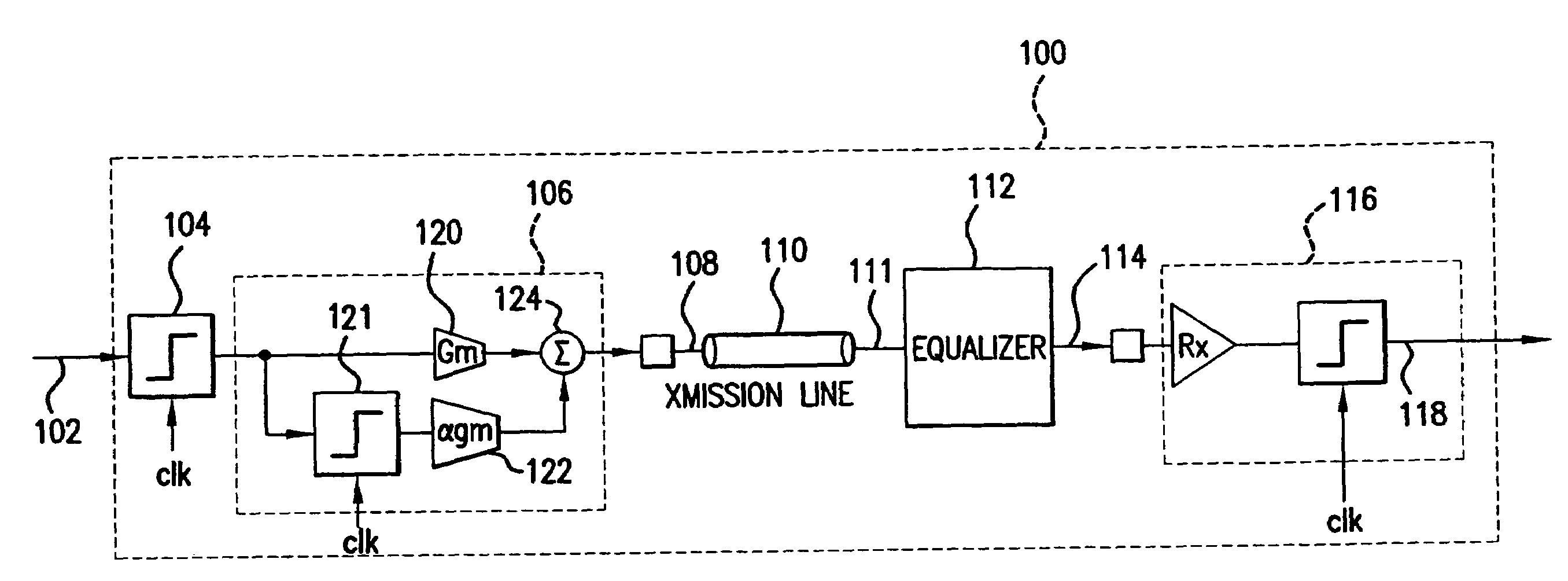
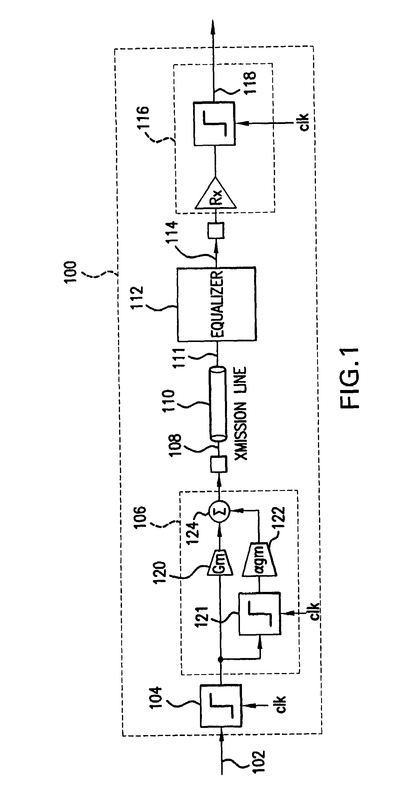
[0020]FIG. 1 illustrates a high speed data link 100 that includes both transmitter de-emphasis and (passive) receiver equalization according to embodiments of the present invention. The High speed data link 100 sends transmit data 102 at a first location to a second location over a transmission line 110 that is output as receive data 118. The transmission line 110 can be optical fiber, coaxial cable, twisted pair, or any other type of transmission media.

[0021]The high speed data link 100 includes a data-synchronization circuit 104, a transmitter de-emphasis circuit 106, a transmission line 110, a passive receiver equalizer 112, and a receive slicer 116.

[0022]The high speed data link 100 can operate at very high data rates, e.g. 3.1 Gbits / sec. At these high data rates, the channel characteristics and distortion change with frequency. In other words, the amplitude and phase characteristics of the transmission line 110 can vary with frequency, causing frequency distortion and inter-sym...


PUM


Abstract

A high speed data link includes transmitter equalization and (passive) receiver equalization to compensate for frequency distortion of the data link. In one embodiment, the transmitter equalization is performed with a de-emphasis circuit. The transmitter de-emphasis circuit pre-distorts an input signal to compensate for at least some of the frequency distortion in the data caused by the transmission line. The (passive) receive equalization circuit further compensates for the frequency distortion at the output of the transmission line to flatten the amplitude response of the output signal, and thereby reduce inter-symbol interference, improve media reach and improve the bit error rate (BER).

Description

CROSS-REFERENCE TO RELATED APPLICATIONS[0001]This application claims the benefit of U.S. Provisional Application No. 60416,578, filed on Oct. 8, 2002, which is herein incorporated by reference in its entirety.BACKGROUND OF THE INVENTION[0002]1. Field of the Invention[0003]The present invention generally relates to high speed data links, and more particularly to high speed data links that utilize transmitter de-emphasis and receiver equalization.[0004]2. Background Art[0005]High speed data links transmit data from one location to another over transmission lines. These data links can include serial data links that receive data in a parallel format and convert the data to a serial format for high speed transmission. SERDES (SERializer DESerializer) data links can be part of a backplane in a communications system, that is well known to those skilled in the art (e.g. Tyco Backplane 30-inch trace).[0006]In high speed data links, there is a trade-off between the length of the data link and...

Claims


Application Information

Patent Timeline
Patent Type & Authority Patents(United States)
IPC IPC(8): H04B3/00H04L25/03H04B3/14
CPCH04L25/03878H04B3/144
Inventor VORENKAMP, PIETERBUCHWALD, AARON
Owner AVAGO TECH INT SALES PTE LTD
Learn More