Phase measurement system

a phase measurement and phase technology, applied in the field of phase measurement systems, can solve the problems of increasing increasing the measurement time, and requiring a larger memory capacity, so as to increase the number of sample images to be stored, increase the measurement time, and increase the memory capacity

Inactive Publication Date: 2009-09-08
KONICA MINOLTA SENSING INC
View PDF10 Cites 9 Cited by
  • Summary
  • Abstract
  • Description
  • Claims
  • Application Information

AI Technical Summary

Benefits of technology

[0010]However, in the method disclosed in Japanese Unexamined Patent Publication No. 2001-108422, the amount of phase shift is the same for all patterns even when the patterns have different pitches. That is, the resolution with which the phase is obtained from a captured image is the same regardless of the pattern pitch. This means that the number of input images required is equal to the number of images required for each pitch multiplied by the number of kinds of pitches. This method, therefore, has had the problem that, if an accurate phase image is to be obtained, the number of sample images to be stored increases, which not only requires a larger memory capacity but greatly increases the measurement time. However, what is needed for phase coupling is to obtain the step function for phase correction. This only requires the resolution just enough to distinguish each step of the step function.
[0012]The present invention has been devised in view of the above situation, and an object of the invention is to reduce the number of input images and shorten the measurement time required to measure the three-dimensional shape of a sample, while retaining the resolution capable of distinguishing each step of the step function needed for phase coupling.
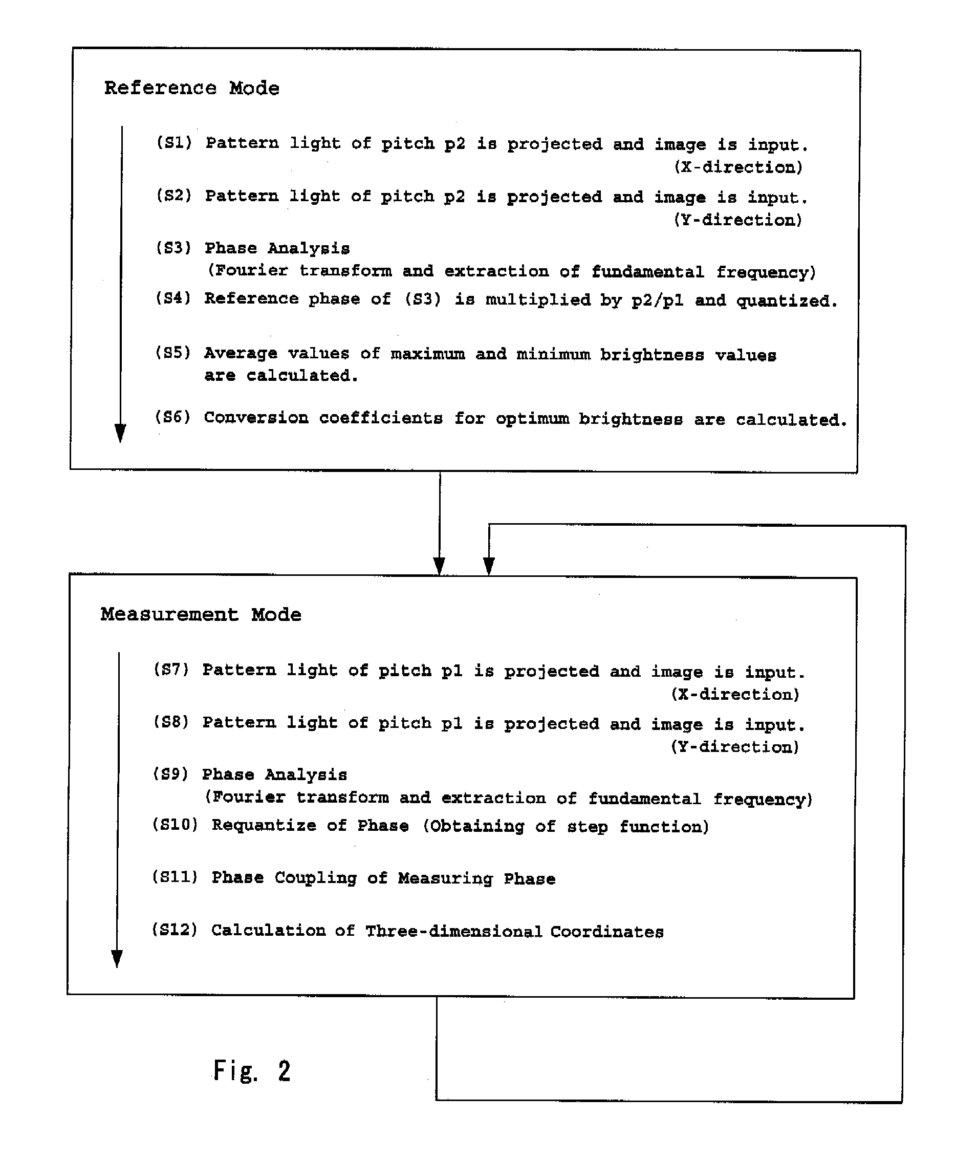
[0017]A rough phase image of the sample is created by performing image-capturing using the pattern light having the first pitch and shifting its phase a minimum required number of times; on the other hand, image-capturing is performed using the pattern light having the second pitch, and an accurate three-dimensional shape of the sample can thus be obtained. Accordingly, the number of first reference images can be reduced to the minimum required, eliminating the need for any extra image input.
[0019]According to the above system, it becomes possible to reduce the measurement time required, for example, for the measurement of a three-dimensional shape. In the process of obtaining measurement data of the sample, the operation of projecting prescribed pattern light and capturing its image has to be performed repeatedly while sequentially shifting the phase of the pattern light. Accordingly, this process has been the most time consuming process in the measurement of a three-dimensional shape. In the above system, since the number of input images of the pattern light having the first pitch can be reduced to the minimum required, the measurement time for the sample can be reduced. Furthermore, since the amount of data to be stored decreases, the required memory capacity can be reduced.

Problems solved by technology

This method, therefore, has had the problem that, if an accurate phase image is to be obtained, the number of sample images to be stored increases, which not only requires a larger memory capacity but greatly increases the measurement time.
On the other hand, the method disclosed in U.S. Pat. No. 6,075,605 has the problem that the configuration of the apparatus becomes complex because the space coding pattern method for obtaining the step function is used in conjunction with the phase shift method used for accurate measurement of the sample shape.

Method used


Image

  • Phase measurement system
  • Phase measurement system
  • Phase measurement system

Examples


Embodiment Construction

[0027]Phase resolution depends on the number, N, of phase shifts performed when inputting the images based on which to obtain the phase. Up to the point where the amount of phase shift is approximately equal to the pixel pitch, the phase resolution is higher as N is larger. Relative resolution a to the brightness amplitude of a projection pattern (resolution which is a times the brightness amplitude) is also a factor that determines the phase resolution. Here, when a beam of light of relative resolution σ is projected and images are captured by shifting the phase of the light N times, the phase obtained from these images is considered to have a theoretical resolution proportional to σ / N.

[0028]Accordingly, if this level of resolution can be obtained as a reference phase, a measuring phase having a longer pitch can be corrected. That is, for any measuring phase in which phase aliasing occurs at a pitch longer than σ / N times the pitch of the reference phase, phase coupling can be accom...


PUM


Abstract

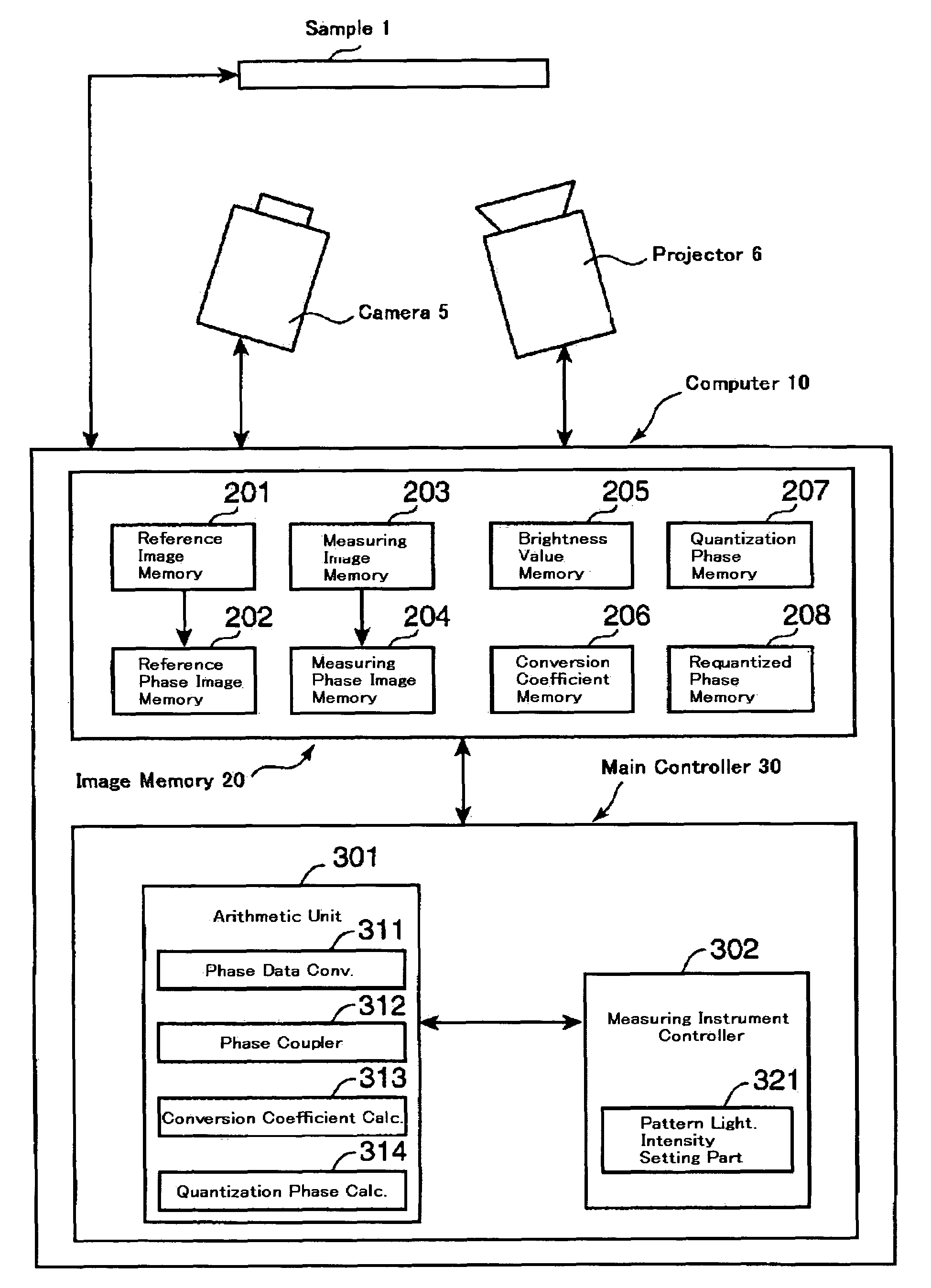
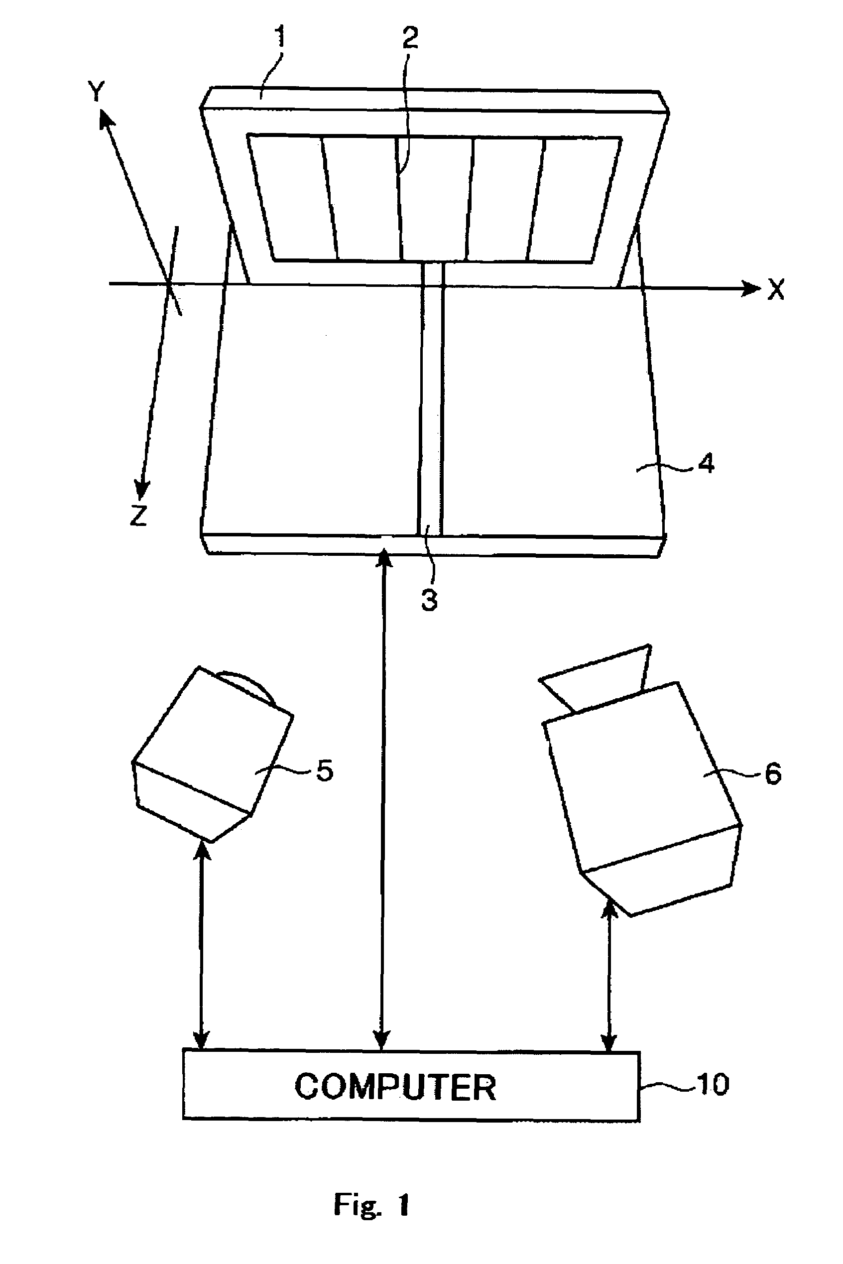
A reference image of a pattern having a first pitch and projected on a sample 1 by a projector 6 is captured by a camera 5. Next, a measuring image of a pattern having a second pitch and projected on the sample 1 by the projector 6 is captured by the camera 5. Here, the second pitch of the pattern light is determined by a value calculated based on the phase resolution of the pattern light having the first pitch. Then, using the reference image thus obtained, phase coupling for the measuring image is performed. The three-dimensional shape of the sample is obtained in this manner.

Description

[0001]This application is based on application No. 2004-179829 filed in Japan, the content of which is hereby incorporated by reference.BACKGROUND OF THE INVENTION[0002]1. Field of the Invention[0003]The present invention relates to a phase measurement system which may be advantageously used, for example, in the measurement of a three-dimensional shape for measuring the shape of a sample by projecting pattern light on the sample and by processing image information obtained by capturing its optical image.[0004]2. Description of the Related Art[0005]As a noncontact method for the measurement of an object's three-dimensional shape, a method called the grating projection method which analyzes the phase distribution obtained from the grating pattern projected on the object is well known in the prior art. The basic components of a measurement apparatus implementing this method are a three-dimensional object (sample), a projector, and a camera. In this arrangement, the camera is disposed i...

Claims


Application Information

Patent Timeline
Patent Type & Authority Patents(United States)
IPC IPC(8): G06K9/40G01B11/24G01B11/25
CPCG01B11/2536
Inventor FUJIWARA, KOJIOJIMA, TAKANOBU
Owner KONICA MINOLTA SENSING INC
Why Eureka
Try Eureka