Image-forming apparatus

a technology of image-forming apparatus and forming container, which is applied in the direction of power drive mechanism, printing, spacing mechanism, etc., can solve the problems of large spacing distance between the upstream and downstream walls in the feeding direction of recording medium, undetectable high cost of manufacture of ink absorber and time-consuming installation of ink absorber in the container, and the back or lower surface contamination problem, etc., to achieve the effect of reducing the risk of ink mist contamination of recording medium, high resolution

Active Publication Date: 2009-09-15
BROTHER KOGYO KK
View PDF18 Cites 20 Cited by
  • Summary
  • Abstract
  • Description
  • Claims
  • Application Information

AI Technical Summary

Benefits of technology

[0011]The present invention was made in view of the background art described above. It is therefore an object of the present invention to provide an image-forming apparatus which permits a non-margin recording operation with a reduced risk of contamination of the recording medium with an ink.
[0014]The provision of the waiting time in the non-margin recording operation permits the movable body to be returned to the recording start position in the main scanning direction only after a larger portion of the ink mist generated from the ink droplets ejected toward the edge portion (e.g., leading end portion) of the recording medium and an area outside the edge portion has fallen onto a medium support portion (e.g., platen) of the apparatus supporting the recording medium. The ink mist which has fallen on the support portion changes into an ink mass, which is not likely to revert into an ink mist. The amount of the ink mist which has fallen and changed into the ink mass increases with an increase of the waiting time provided before the moment of initiation of the subsequent movement of the movable body following the movement of the movable body during which the non-margin recording operation is performed. In other words, the amount of the ink in the form of a mist at the moment of initiation of the subsequent movement of the movable body can be reduced by providing the waiting time, so that the amount of the ink mist which floats in a space between the recording head and the recording medium during the subsequent movement of the movable body can be reduced by providing the waiting time. Thus, the provision of the waiting time before initiation of the subsequent movement of the movable body is effective to prevent the non-margin recording operation with intermittent movements of the recording head with the movable body in a misty state of the ink floating between the recording head and the recording medium, whereby a risk of contamination of the recording medium with the ink mist can be significantly reduced. In particular, the provision of the waiting time is effective to reduce the risk of contamination of the back surface of the recording medium with the ink mist during the return movement of the movable body to the recording start position.
[0015]A recent demand for a high resolution of image reproduction requires size reduction of the ink droplets, which leads to easier generation of the ink mist and a tendency toward an increased amount of generation of the ink mist. However, the provision of the waiting time according to the present invention permits the movable body and recording head to be returned to the recording start position only after the amount of the floating ink mist is reduced, making it possible to perform the recording operation for a high-quality image formed with ink droplets of a small size, while preventing or reducing the risk of contamination of the recording medium with the ink mist.
[0016]Where the control device includes the speed control portion also operable in the non-margin recording operation, the speed control portion controls the driving device such that the movement of the movable body in one of the opposite directions during which the non-margin recording is performed by the recording head is followed by the movement of the movable body in the other direction at a lower speed which is lower than that of the movement in the above-indicated one direction. The movement of the movable body at the lower speed in the other direction is effective to reduce a risk of contamination of the recording medium with an ink mist generated in the movement of the movable body in the above-indicated other direction.
[0017]The driving device to move the movable body is usually controlled by a control device such that the movable body is moved at a predetermined fixed speed which is determined to assure a desired quality of the image formed by the ink droplets ejected by the recording head. The speed control portion of the control device according to the present invention, the movable body is returned in the above-indicated other direction to the recording start position at the lower speed lower than that of the movement of the movable body in the above-indicated one direction during which the non-margin recording operation is performed. The reduction of the speed of the return movement of the movable body in the above-indicated other direction to the recording start position is effective to reduce the volume of air flow caused by that movement, and is accordingly effective to reduce the amount of the ink mist floating between the recording head and the recording medium. Therefore, the reduction of the speed of the return movement is effective to reduce the risk of contamination of the recording medium with an ink mist generated by the ink droplets ejected toward the edge portion (e.g., leading end portion) of the recording medium and an area outside the edge portion. In particular, the reduction of the speed of the return movement of the movable body is effective to reduce the risk of contamination of the back surface of the recording medium with the ink mist during the return movement of the movable body.
[0018]The reduction of the speed of the movement of the movable body in the above-indicated other direction by the speed control portion is also effective to reduce the amount of the ink mist floating between the recording head and the recording medium during the movement of the movable body in the above-indicated other direction, making it possible to perform the recording operation for a high-quality image formed with ink droplets of a small size, while preventing or reducing the risk of contamination of the recording medium with the ink mist.

Problems solved by technology

The ink droplets deposited on the platen cause a problem of contamination of the back or lower surface of the following recording media when these media are slidably moved on the platen.
To assure a high degree of freedom of the recording medium from its contact with the ink absorber, the ink absorber must be accurately dimensioned and carefully installed within the container, undesirably requiring a high cost of manufacture of the ink absorber and time-consuming installation of the ink absorber in the container.
For effective absorption of the ink droplets by the ink absorber, on the other hand, it is necessary to form the platen with a sufficiently large area of opening of the container, so that the spacing distance between the upstream and downstream walls in the feeding direction of the recording medium is inevitably made large.
Accordingly, the back surface of the recording medium may be contaminated with the ink at its leading and trailing end portions.
The non-margin recording operation has another drawback that the ink droplets ejected outside the recording medium cause an ink mist that also undesirably contaminates the recording medium, particularly, its back surface.

Method used


Image

  • Image-forming apparatus
  • Image-forming apparatus
  • Image-forming apparatus

Examples


Embodiment Construction

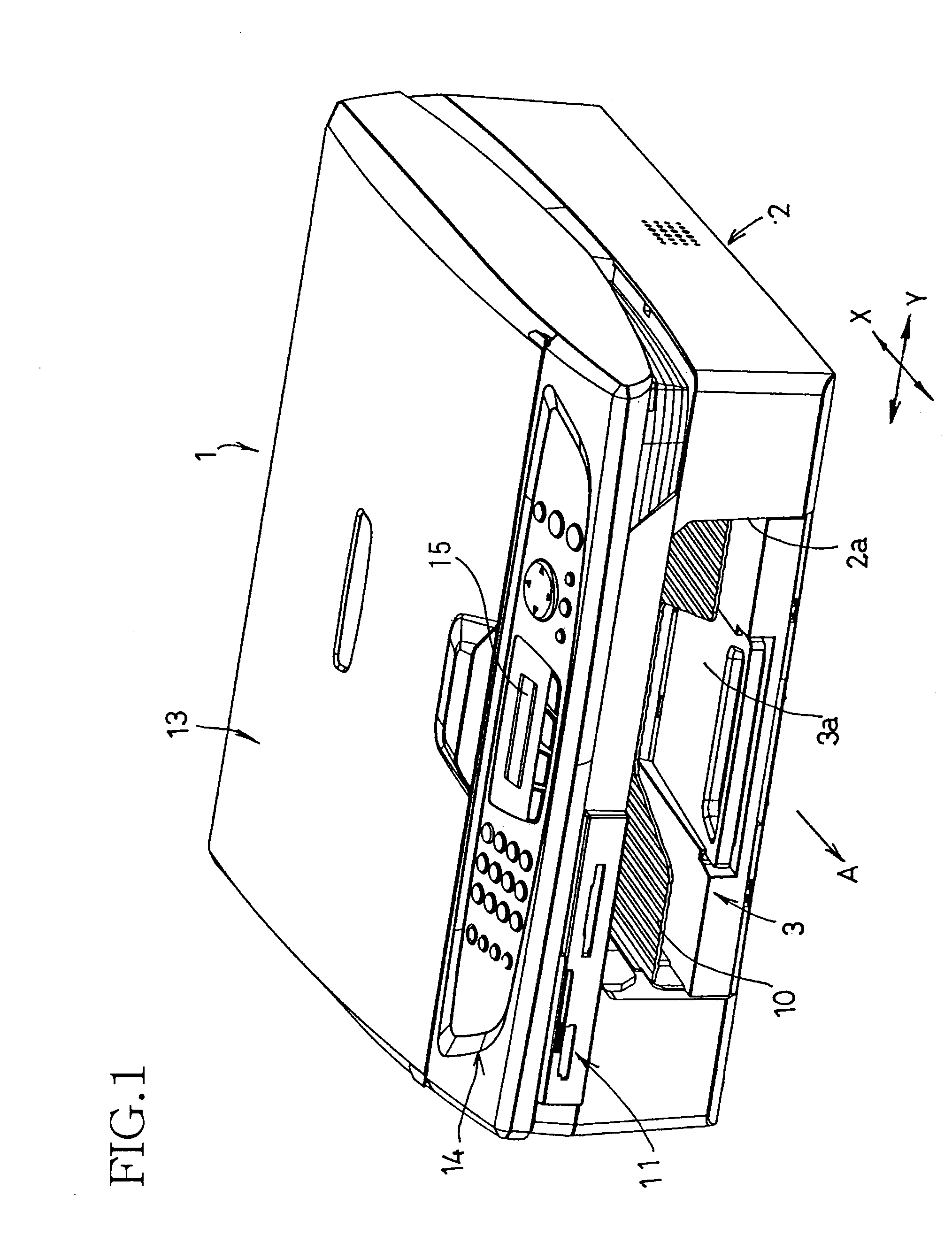
[0029]Referring to FIGS. 1-3, there is shown an image-forming apparatus 1 in the form of a multi-function device (MFD) constructed according to one embodiment of the present invention, which has a printing function, a copying function, a scanning function and a facsimile (telecopier) function. However, the Image-forming apparatus 1 may be an ink-jet printer having only the printing function. Although a recording medium on which an image is recorded by the image-forming apparatus 1 is a sheet of paper P in the present embodiment, the recording medium may be any other kinds of sheets such as a plastic film.

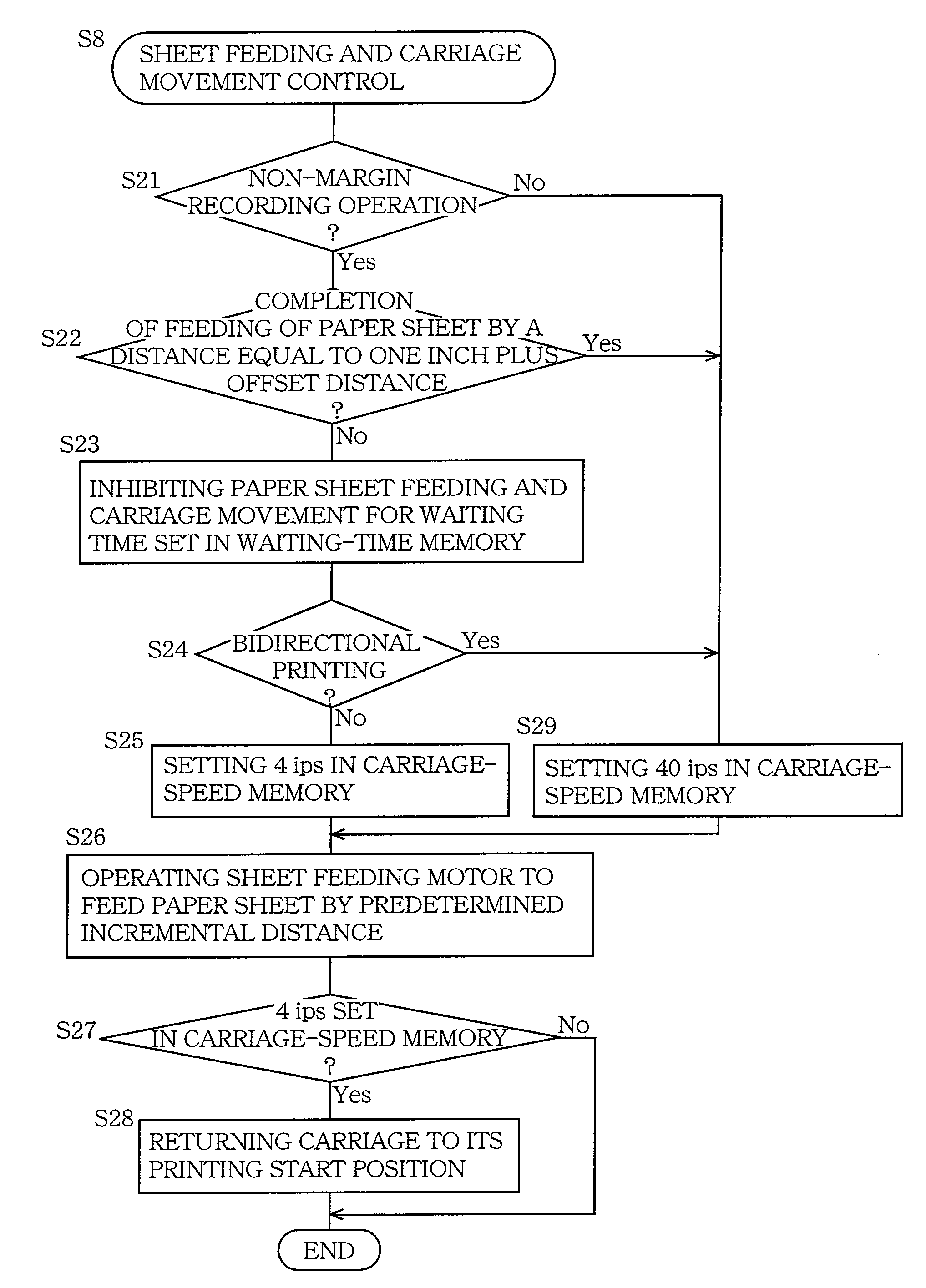
[0030]The image-forming apparatus 1 is capable of performing not only a normal printing (recording) operation with top, bottom and side margins, but also a non-margin printing (recording) operation without the top and bottom margins being left along the leading and trailing edges of the paper sheet P (but with the right and left margins being left along the right and left edges of t...


PUM


Abstract

An image-forming apparatus is capable of performing a non-margin recording operation without a margin on a recording medium and providing a waiting time between a moment of termination of a movement of a carriage in one of opposite directions and a moment of initiation of a subsequent movement of the carriage in the other direction, if the non-margin recording operation is performed during the movement of the carriage in the above-indicated one direction. The carriage is moved in the other direction (returned) at a speed lower than that of the movement in the above-indicated one direction, so that the back surface of an edge portion (e.g., leading end portion) of the recording medium is protected from contamination with an ink mist produced from the ink droplets. The waiting time and the return speed of the carriage can be manually selected or changed by using an operator's control panel, so that the non-margin recording operation can be performed in a desired manner (in a high-image-quality mode or a high-speed mode).

Description

[0001]The present application is based on Japanese Patent Application No. 2004-289359 filed on Sep. 30, 2004, the contents of which are incorporated herein by reference.BACKGROUND OF THE INVENTION[0002]1. Field of the Invention[0003]The present invention relates in general to an image-forming apparatus, and more particularly to an image-forming apparatus arranged to be capable of performing a so-called “non-margin recording operation”, namely, an operation to record an image, without a margin left along an edge of a recording medium (e.g., a sheet of paper), for example, to record an image over an entire length of the recording medium, without top and bottom margins being left on a recording surface of the recording medium,[0004]2. Discussion of Related Art[0005]In a conventional printer of ink-jet type, a recording head has a nozzle surface in which ink-ejecting nozzles are open, and is mounted on a carriage reciprocable in a main scanning direction, such that the nozzle surface fa...

Claims


Application Information

Patent Timeline
Patent Type & Authority Patents(United States)
IPC IPC(8): B41J29/38B41J11/42B41J19/00
CPCB41J11/0065
Inventor KOGA, YUJIKOIDE, SHOHEIOUCHI, TETSUYA
Owner BROTHER KOGYO KK
Why Eureka
Try Eureka