Image forming device and method using intermittent motion across a work surface

Inactive Publication Date: 2009-09-15
NISNEVICH LEV +1
View PDF2 Cites 20 Cited by
  • Summary
  • Abstract
  • Description
  • Claims
  • Application Information

AI Technical Summary

Benefits of technology

[0049]The contact means play a vital role in the accuracy achieved as they ensure holding contact between a part of the device and the part's bearing surface in the course of operation and for executing a displacement step. Several presented contact means are novel and make possible operations on different surfaces without loss in accuracy.
[0050]The present invention also provides a movement appliance for incrementally moving operating tools. The movement appliance can deliver tools or articles to specific locations on the surface with high accuracy.

Problems solved by technology

Since the medium must be fed into an image forming device, an image cannot be transferred to or received from a rigid substrate or other medium that cannot be fed into the stand-alone image forming device.
Any vibrations or other disturbances may produce small alterations in the frame position relative to the printing surface during printing process and prevent high accuracy printing.
Lateral guide rails may be used to help prevent drift of the beginning of the

Method used


Image

  • Image forming device and method using intermittent motion across a work surface
  • Image forming device and method using intermittent motion across a work surface
  • Image forming device and method using intermittent motion across a work surface

Examples


first embodiment

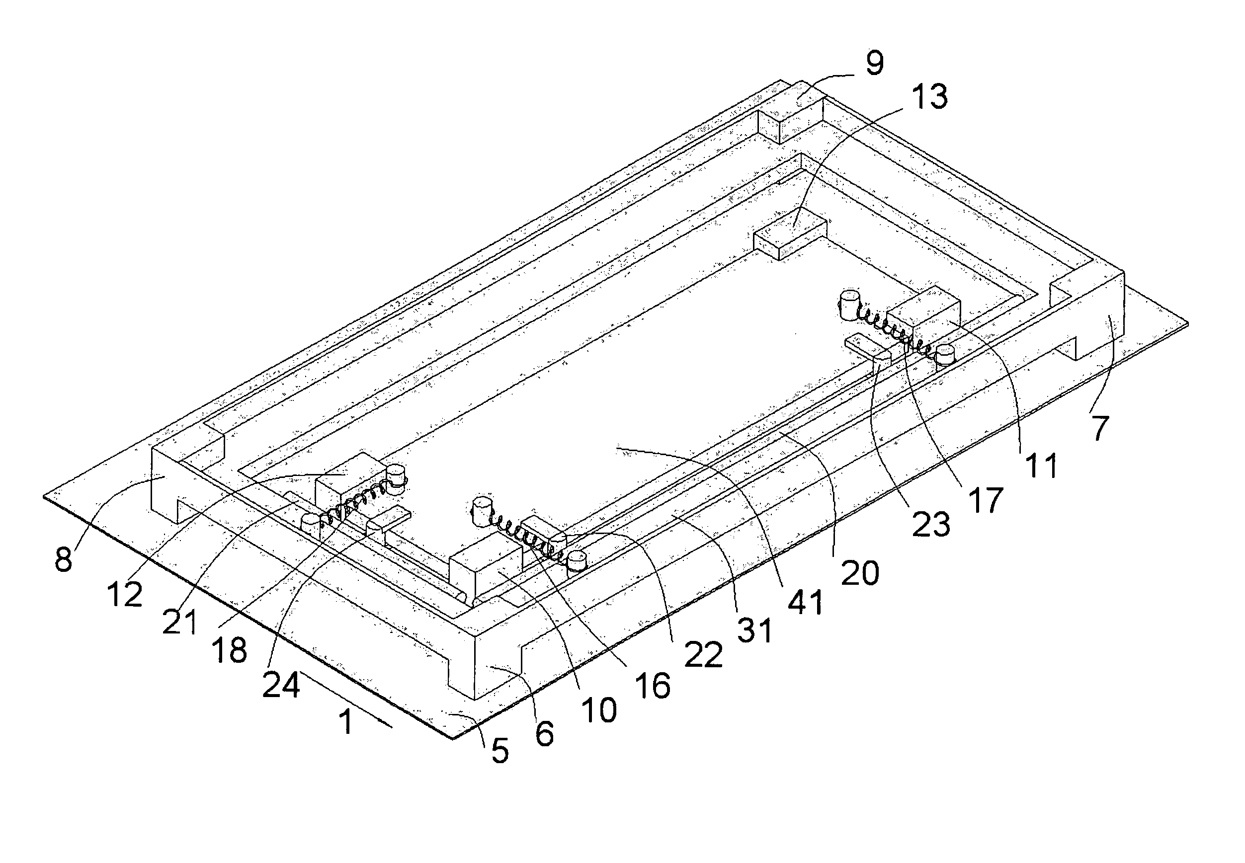
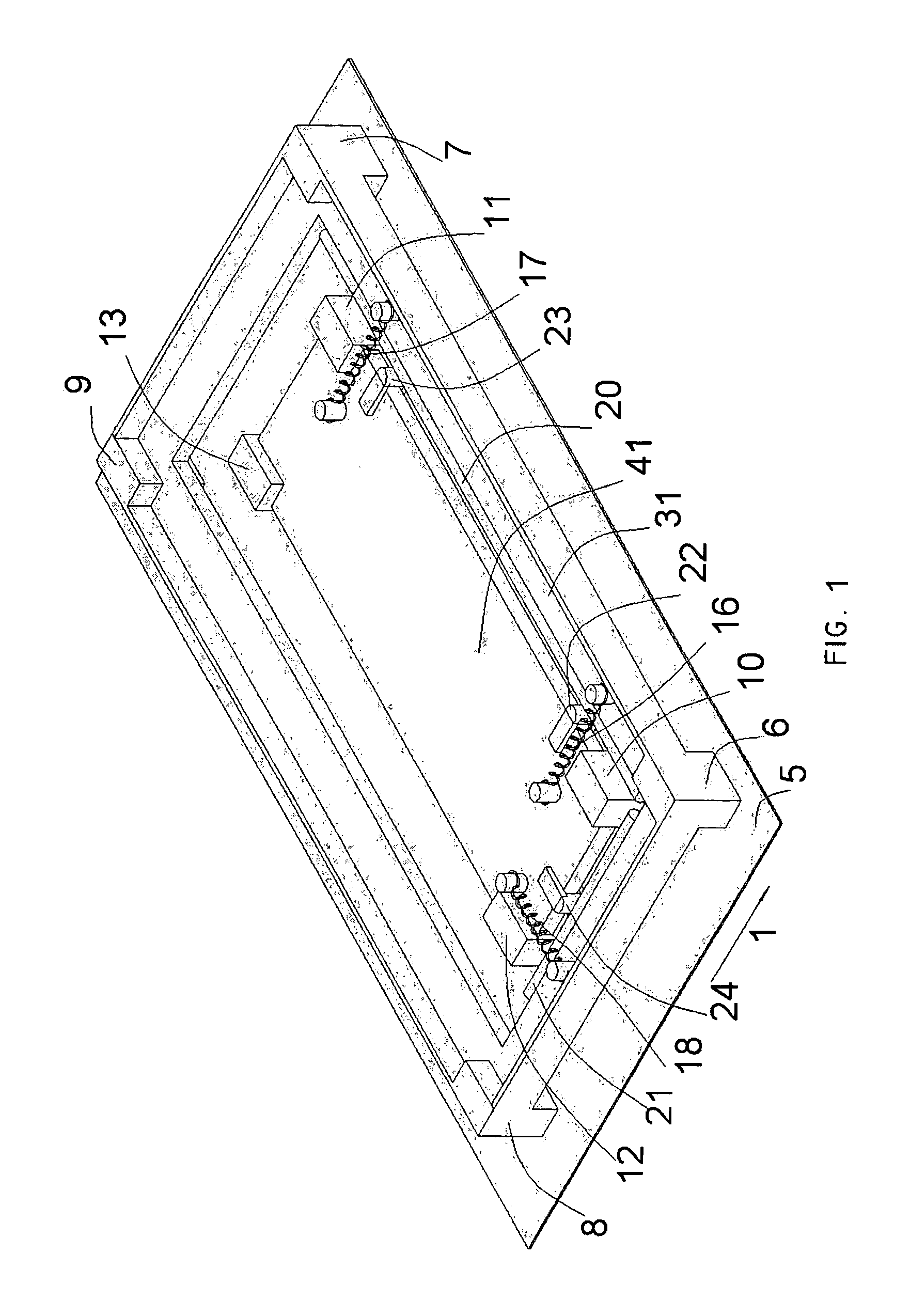
[0113]Referring first to FIG. 1, there are basic elements of the device for accurate incremental displacement that step-wise translates itself across a work surface. Two main parts of this embodiment are the frame 31 and the shuttle 41. The Supports 6, 7, 8, 9 are rigidly fixed to the frame 31. The Supports 10, 11, 12, 13 are rigidly fixed to the shuttle 41. The shuttle and the frame are clamped to each other by springs or by other elastic bodies 16, 17 and 18. The springs 16, 17 pull the main rod 20 (a horizontal cylinder rigidly fixed to the inner edge of the frame 31) to pins 22, 23 (a vertical cylinders rigidly fixed to the outer edge of the shuttle 41). Let an axis of the rod 20 be perpendicular to the printer movement direction 1. The spring 18 of the shuttle pulls the side rod 21 (a horizontal cylinder rigidly fixed to the inner edge of the frame 31) to the pin 24 (a vertical cylinder rigidly fixed to the outer edge of the shuttle 41). Let an axis of the rod 21 be parallel to...

second embodiment

[0202]the device for accurate incremental displacement is shown in FIG. 21. Two main parts of this embodiment are the frame 131 and the shuttle 141. The supports 106, 107, 108, 109 are rigidly fixed to the frame 131. The supports 110, 111, 112, 113 are rigidly fixed to the shuttle 141. The shuttle and the frame are clamped to each other by the tension springs 116, 117, or by the compression spring 118 (elastic material, or couple of magnets, or the like can be used in place of springs). The springs 116, 117 clamp spacers 133, 135 between the horizontal rod 120 (rigidly fixed above the shuttle to the upper beams of the frame) and pins 122, 123 (vertical pins rigidly fixed to the shuttle). The spring 118 is fixed to the shuttle and pulls the horizontal rod 121 (rigidly fixed to the frame and protruding above the shuttle) to the vertical pin 124 rigidly fixed to the shuttle thus clamping the spacer 132 between the rod 121 and the pin 124. Each spacer is driven by a separate stepping mo...

third embodiment

[0232]FIG. 29 shows a front-left isometric view of the device which is an exemplifying version of the incrementally moving inkjet printer. It comprises three basic parts: the y-shuttle 241, shown separately in FIG. 29A, the frame 231, shown separately in FIG. 29B and the x-shuttle 270, shown separately in FIG. 29C. Top view of the frame with the y-shuttle is shown in FIG. 29D and FIG. 32, 32A, 32B, 32C show left view of the printer with a sectional view of the frame.

[0233]The Y-Shuttle:

[0234]The y-shuttle 241 and its interoperation with the frame 231 are designed like a modified second embodiment of the device with some changes.

[0235]The y-shuttle comprises two supports that are at the left and right ends of the shuttle. There are two identical and symmetrically positioned spacers, 232 and 233, each of which is driven synchronously but in the opposite directions through the transmission system 281 by the stepping motor 292.

[0236]Each spacer (FIG. 30) of the printer has two levels. T...


PUM


Abstract

A method and device for forming an image on various types of work surfaces and/or copying an image from a work surface to a computer memory. The device forms an image portion by portion, each portion being formed while the device is motionless at the stoppages between displacements thereof. The device includes means for enabling placing subsequently formed image portions with proper spatial relationship to the portions formed earlier in order to form an accurate image. The device comprises two or more rigid structures moving relative to each other each having contact means for engagement and release of the rigid structures to and from the work surface.

Description

REFERENCE TO RELATED APPLICATIONS[0001]This application is a continuation of application Ser. No. 11 / 246,244, filed Oct. 11, 2004, now abandoned, which claims the benefit of provisional patent application 60 / 617,972, filed Oct. 12, 2004 by the present inventors.FIELD OF INVENTION[0002]The present invention relates to image forming methods, systems and devices like printers, scanners, engravers, marking devices and alike.BACKGROUND OF THE INVENTION[0003]When an area of an image to be treated is larger than the image forming device, or the image medium cannot be loaded or inserted into the device, the device must be moved relative to the medium.[0004]Hereinafter the term “image forming device” includes a variety of scanners, different surface mapping devices, surface inspection devices, printers (including those using inkjet, thermal and laser printing), plotters, marking and engraving devices, image-wise material deposition or removal devices, which are intended to read an image from...

Claims


Application Information

Patent Timeline
IPC IPC(8): B41J25/00
CPCB41J2/16526B41J2/16538H04N1/10B41J3/36H04N2201/0426
Inventor NISNEVICH, LEVSTEIN, MARINA BORODINA
Owner NISNEVICH LEV
Why Eureka
Try Eureka