Magnetic shield panel

a shield panel and magnetic shield technology, applied in the field of magnetic shield panels, can solve the problems of taking a lot of labor and time, and achieve the effect of easy construction and easy observation of conditions

Inactive Publication Date: 2009-09-15
NITTETABU STEEL SHEET CORP +1
View PDF23 Cites 6 Cited by
  • Summary
  • Abstract
  • Description
  • Claims
  • Application Information

AI Technical Summary

Benefits of technology

[0004]The present invention has been accomplished in view of the above points of the prior art. It is an object of the present invention to provide a magnetic shield panel, the magnetic shield members of which can be easily constructed and the shapes of which can be positively maintained. It is another object of the present invention to provide a magnetic shield panel, the visibility through which can be ensured so that a patient can feel easy about being in the magnetic shield room and further a doctor can easily observe a condition of the patient.
[0008]According to the present invention, by forming a panel with a magnetic shield member integrated with a metallic plate or a translucent plate member, the magnetic shield member can be easily applied. Further, by the metallic plate or the translucent plate member, the magnetic shield member can be protected, and a deformation and damage, which are caused when an external force is carelessly given to the magnetic shield member, can be prevented, and the shape of the magnetic shield member can be properly maintained.
[0009]Especially when a translucent plate member is used as a face plate, the visibility in a room, in which a magnetic field forming apparatus such as MRI is arranged, can be ensured. Therefore, a patient can feel easy about being in the magnetic shield room and further a doctor can easily observe a condition of the patient.

Problems solved by technology

However, it takes much labor and time to arrange a large number of magnetic shield strip members along the walls in parallel to each other while leaving a gap between them.

Method used


Image

  • Magnetic shield panel
  • Magnetic shield panel
  • Magnetic shield panel

Examples


Embodiment Construction

[0058]The most preferred embodiment of the present invention will be explained as follows.

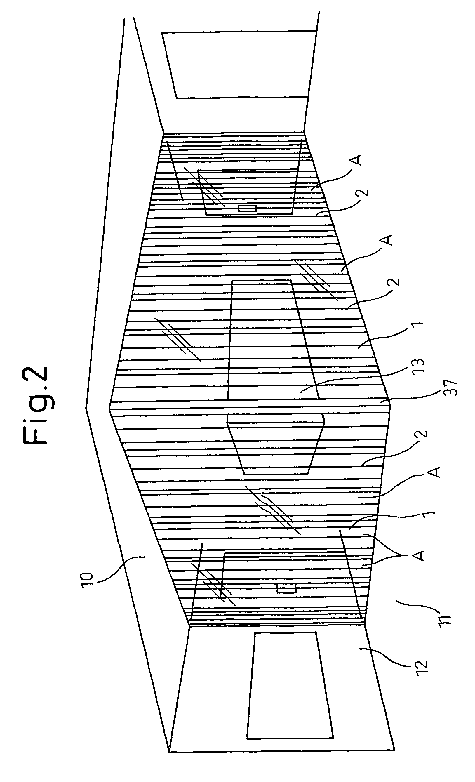
[0059]FIG. 2 is a view showing an example of the magnetic shield room of the present invention.

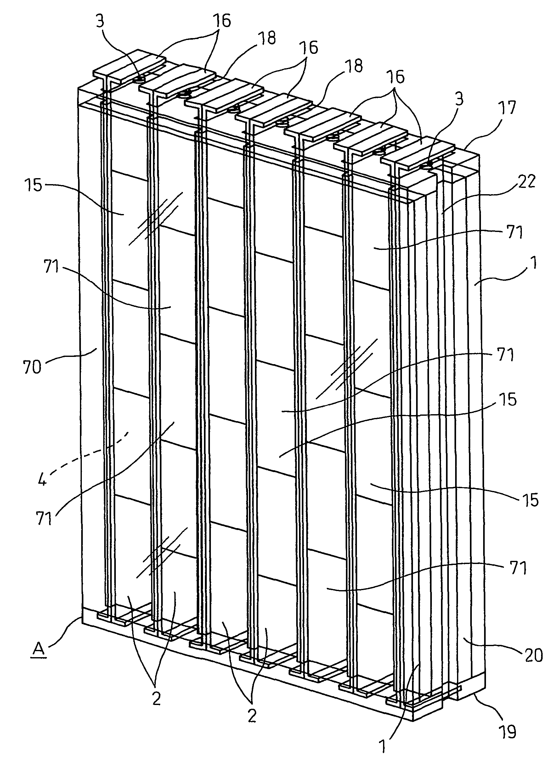
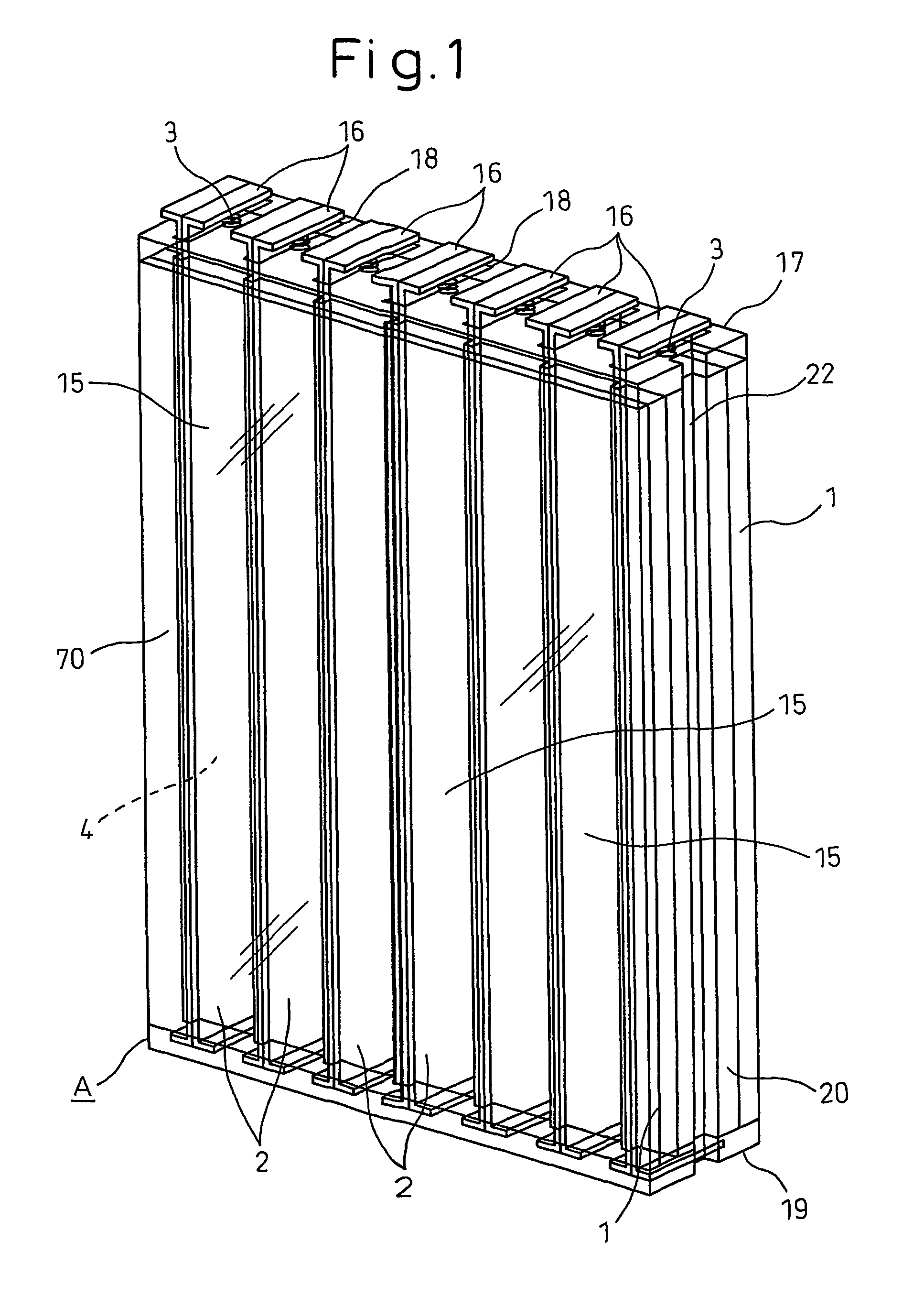
[0060]In this magnetic shield room, two walls 12, which are adjacent to each other, among the ceiling 10, the floor 11 and the four walls, are formed of magnetic shield panels A of the present invention. The magnetic shield panel A is of a vertical type in which magnetic shield members 2 vertically and longitudinary extend. In the present invention, the longitudinal direction of the magnetic shield member 2 may be directed in any direction. However, for example, it is preferable that the longitudinal direction of the magnetic shield member 2 is arranged substantially in parallel to the direction of the magnetic field to be shielded. In the magnetic shield room shown in FIG. 2, since the magnetic field generated from the magnetism generation source 13 such as MRI is formed being directed in the perpend...


PUM


Abstract

A magnetic shield panel includes a magnetic shield member made of magnetic material; and a metallic plate or a translucent plate member, wherein the magnetic shield member is attached to the metallic plate or the translucent plate member.

Description

TECHNICAL FIELD[0001]The present invention relates to a magnetic shield panel used for shielding an influence of magnetism emitted from facilities, in which magnetism is used, to the outside, and also used for shielding an influence of magnetism given to the facilities from the outside.BACKGROUND ART[0002]On the other hand, the official gazette of Japanese Unexamined Patent Publication No. 2002-164686 discloses an open type magnetic shield method. A magnetic shield room is defined by walls on which a plurality of magnetic shield members, each of which comprises a plurality of strips of magnetic shield material on each other, are arranged perpendicularly along the walls parallel to each other so that the magnetic flux density (the magnetic field intensity) can be attenuated between the opposed faces of the magnetic shield members adjacent to each other.[0003]However, it takes much labor and time to arrange a large number of magnetic shield strip members along the walls in parallel to...

Claims


Application Information

Patent Timeline
Patent Type & Authority Patents(United States)
IPC IPC(8): H05K9/00H02B1/44E04B1/92E04B2/74E04B2/82
CPCE04B2/7448E04B2/824E04B2/7453E04B2001/925E04B1/92E06B5/10H05K9/00
Inventor MATSUMOTO, MORIHIROOKUZAKI, YUJIMINO, JIROHYAMADA, YONEOSAITO, TAKESHIHAMANO, TAKUBI
Owner NITTETABU STEEL SHEET CORP
Why Eureka
Try Eureka