
Programmable voltage regulator with dynamic recovery circuits

a voltage regulator and dynamic recovery technology, applied in logic circuits, instruments, and increasing the modification of reliability, etc., can solve the problems of system designers not being designer will not be able to justify the addition of additional components for producing 1.8 volt power supply, and designer may not be able to easily accommodate complex power supply voltage requirements

Inactive Publication Date: 2009-09-15
ALTERA CORP
View PDF23 Cites 48 Cited by
  • Summary
  • Abstract
  • Description
  • Claims
  • Application Information

AI Technical Summary

Benefits of technology

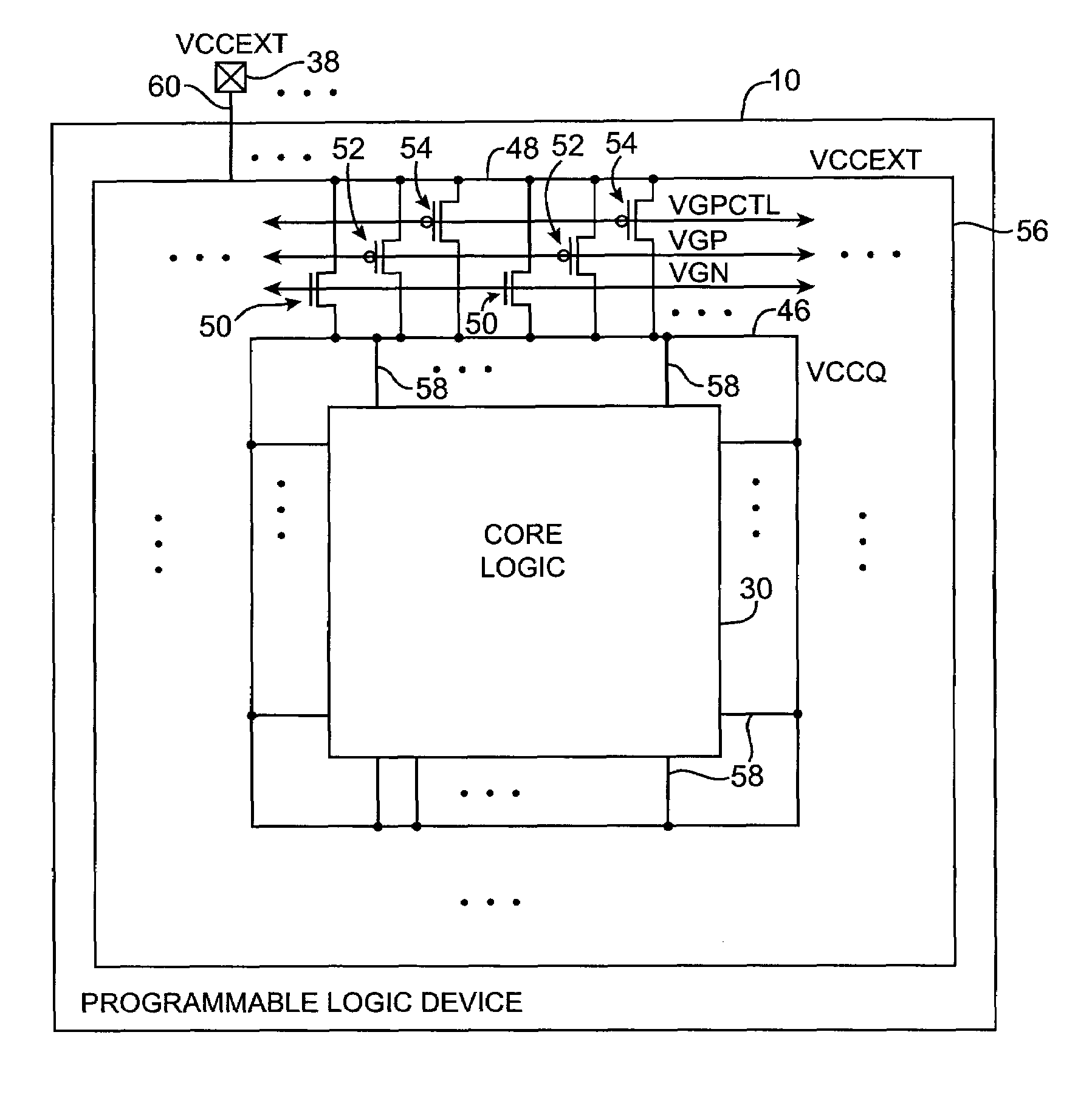
[0008]In accordance with the present invention, voltage regulator circuitry is provided that can reduce potentially large external power supply voltage levels to the lower levels used by core logic on a programmable logic device. An external power supply voltage may be connected to a first bus. A core logic power supply voltage may be distributed to core logic using a second bus. The first and second busses may be connected by a ring of n-channel metal-oxide-semiconductor and p-channel metal-oxide-semiconductor transistors.

Problems solved by technology

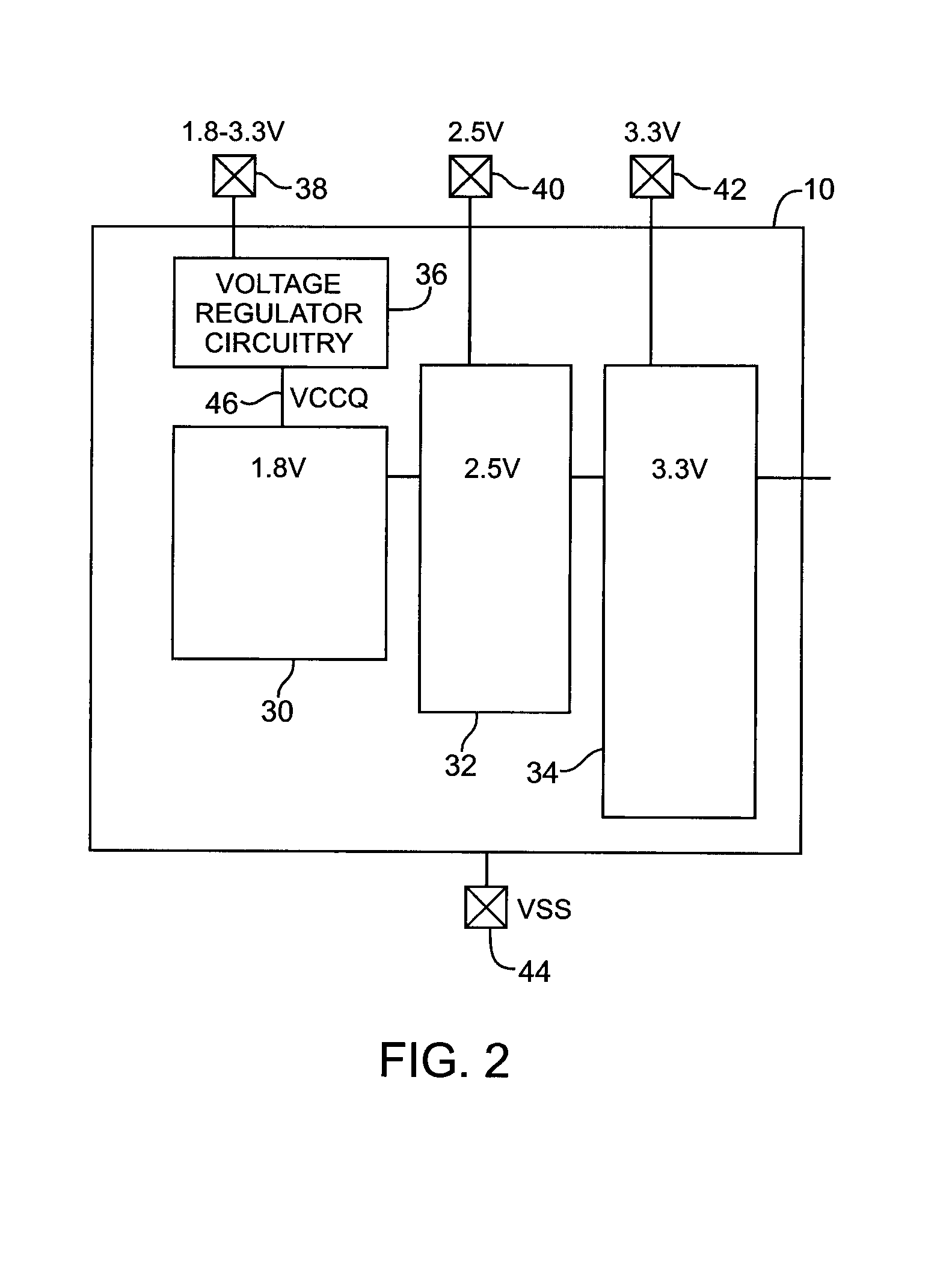
Although there are important performance benefits involved in using multiple power supply voltages in a programmable logic device, some system designers may not be able to easily accommodate complex power supply voltage requirements.
For example, if a system is being designed that uses 3.3 volt power for all of its major components, it may be burdensome for the system designer to add extra circuitry to produce a 1.8 volt power supply to accommodate a programmable logic device.
Unless the need is great enough, the designer will not be able to justify the additional components for producing the 1.8 volt power supply and will be forced to use a lower-performance programmable logic device that does not require a 1.8 volt supply to operate its core logic.

Method used


Image

  • Programmable voltage regulator with dynamic recovery circuits
  • Programmable voltage regulator with dynamic recovery circuits
  • Programmable voltage regulator with dynamic recovery circuits

Examples


Embodiment Construction

[0024]The present invention relates to voltage regulators with dynamic regulation capabilities. The voltage regulator circuitry of the present invention may be provided on integrated circuits to allow them to accommodate a range of external power supply voltages. This allows the integrated circuit to include high-performance low-voltage core logic even when a system designer is not able to provide a low-voltage power supply on the board or other system component in which the integrated circuit is installed.

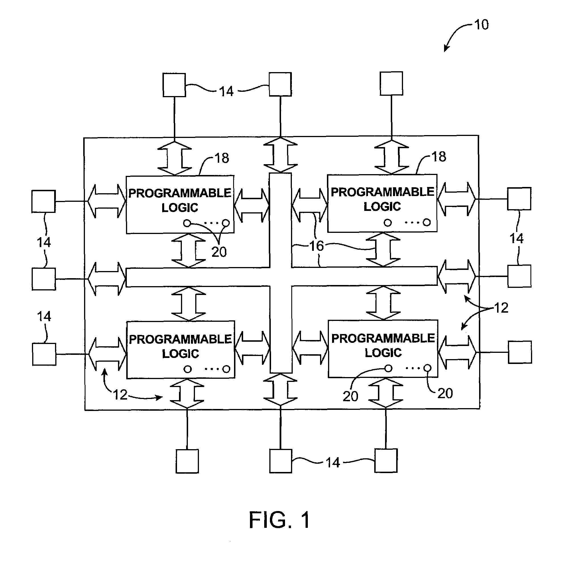
[0025]The integrated circuits with low-voltage core logic that are provided with voltage regulator circuitry in accordance with the invention may be, for example, programmable logic device integrated circuits such as programmable logic devices with programmable non-volatile configuration memory. The invention also applies to integrated circuits with programmable capabilities that are not typically referred to as “programmable logic devices.” Such programmable integrated circuits m...


PUM


Abstract

Voltage regulator circuitry is provided. The voltage regulator circuitry is suitable for powering core logic on a programmable logic device. The voltage regulator circuitry receives an external power supply voltage and reduces the external power supply voltage to a core power supply voltage if needed. If the external power supply voltage is at the same level needed to power the core logic, the voltage regulator circuitry passes the power supply voltage to the core logic. The voltage regulator circuitry monitors the core power supply voltage using a feedback path. Overshoot and undershoot fluctuations are minimized. The external power supply voltage may be supplied to a first bus. The core power supply voltage may be distributed on a second bus. A ring of transistors may be used to convey power from the first bus to the second bus. Control circuitry may control the ring of transistors based on programmable setpoint voltages.

Description

BACKGROUND OF THE INVENTION[0001]This invention relates to programmable logic device integrated circuits, and more particularly, to voltage regulator circuitry for producing a fixed internal power supply voltage from a range of potential external supply voltages.[0002]Programmable logic devices are a type of integrated circuit that can be customized by a user to implement a desired logic design. In a typical scenario, a logic designer uses a logic design system to design a logic circuit. The logic design system uses information on programmable logic device hardware capabilities to help the designer implement the logic circuit. The logic design system creates configuration data. When the configuration data is loaded into the programmable logic device, it programs the logic of the programmable logic device so that the programmable logic device implements the designer's logic circuit.[0003]Modern high performance programmable logic devices sometimes use multiple power supply voltages. ...

Claims


Application Information

Patent Timeline
IPC IPC(8): G05F1/10G05F3/02
CPCG05F1/56
Inventor BUI, JOHN
Owner ALTERA CORP
Learn More