Tactile display device and touch panel apparatus with tactile display function using electrorheological fluid
a technology of touch panel apparatus and tactile display, applied in the field of tactile display devices, can solve the problems of ineffective heavy-duty operation and reduce efficiency, and achieve the effect of effectively displaying tactile information
- Summary
- Abstract
- Description
- Claims
- Application Information
AI Technical Summary
Benefits of technology
Problems solved by technology
Method used
Image
Examples
first embodiment
(Structure of Touch Panel Apparatus 10)
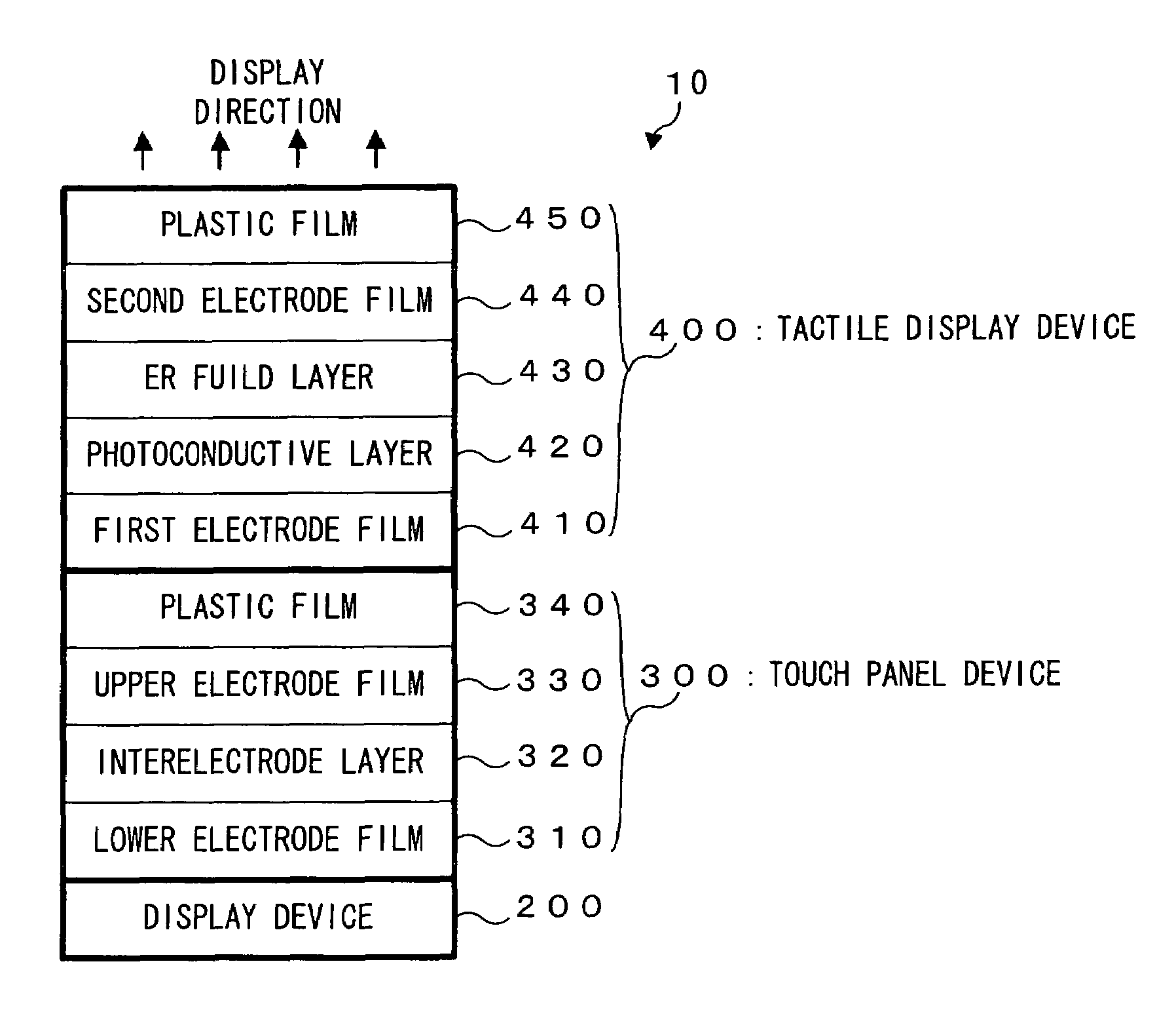
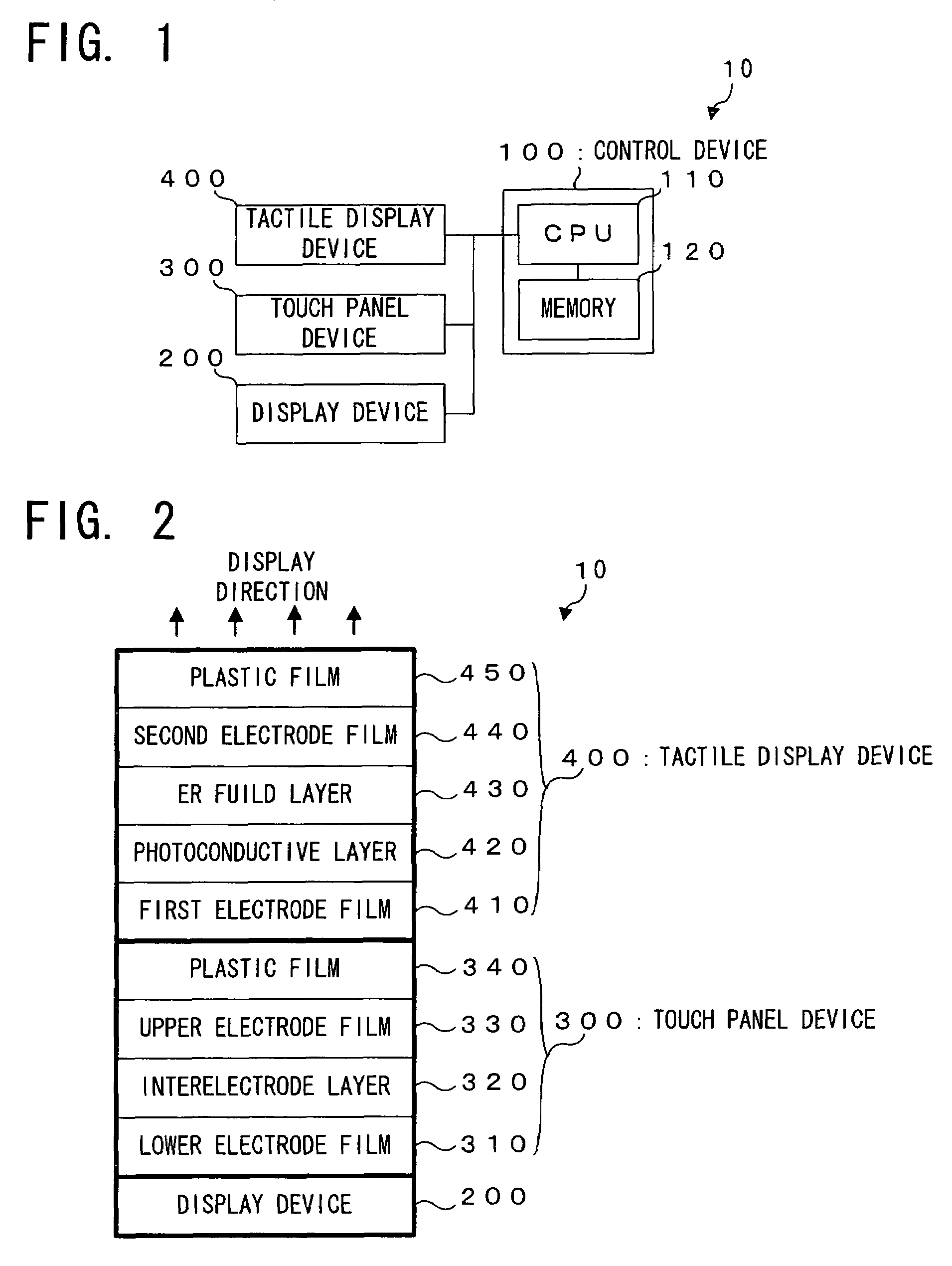
[0056]First of all, an explanation will be made on a structure of the touch panel apparatus with tactile display function according to the first embodiment of the invention (hereinafter referred to as a “touch panel apparatus 10” as appropriate), with reference to FIG. 1. FIG. 1 shows the touch panel apparatus 10 in a block diagram.
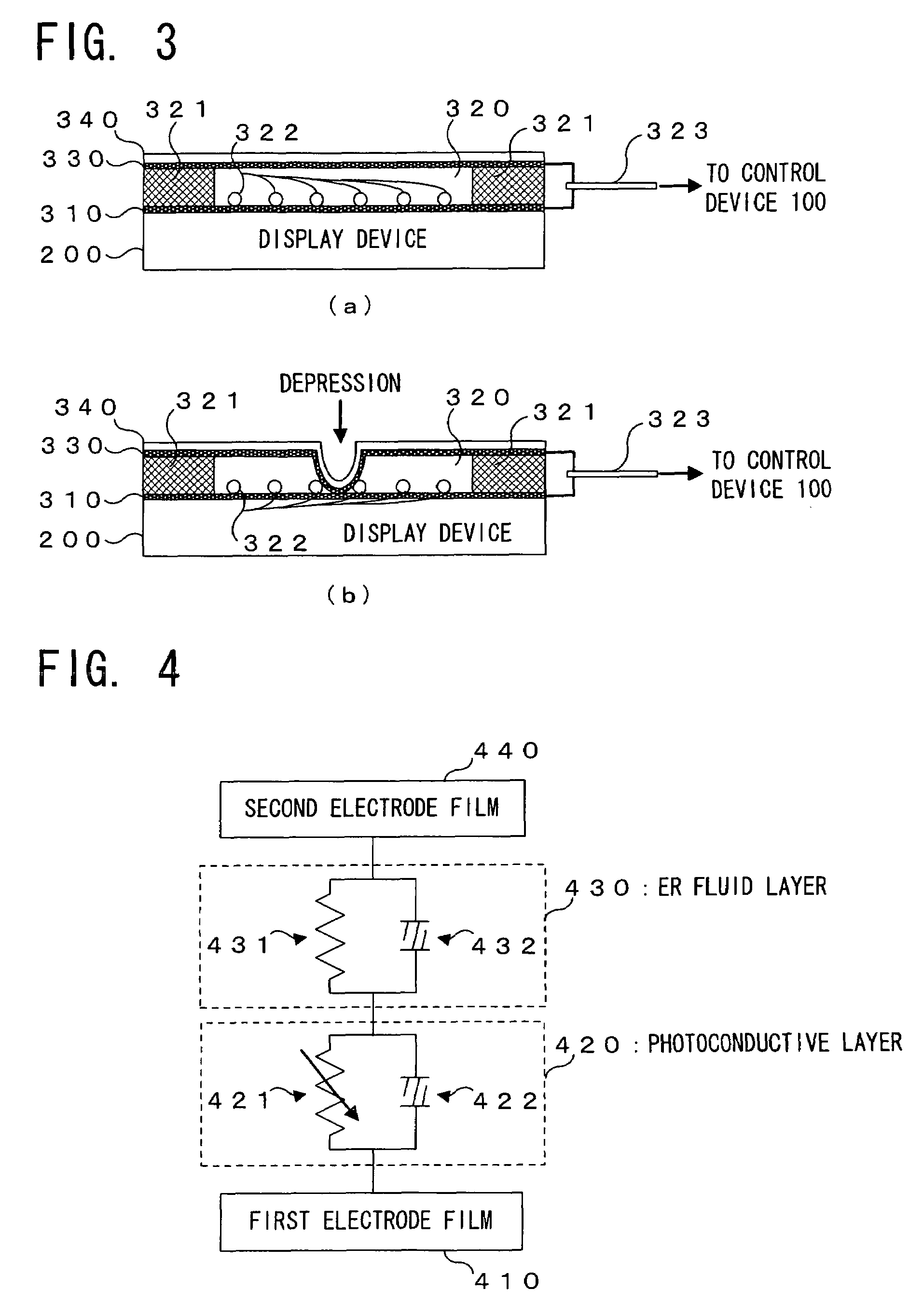
[0057]In FIG. 1, the touch panel apparatus 10 is provided with: a control device 100; a display device 200; a touch panel device 300; and a tactile display device 400. The touch panel apparatus 10 is an example of the touch panel apparatus with tactile display function according to the present invention, which is constructed in such a manner that information can be inputted via the touch panel device 300, with the tactile information inputted via the tactile display device 400, on the basis of various key images, such as numerics or characters, visually displayed on the display device 200.
[0058]The control device 100...
second embodiment
[0096]In the aforementioned first embodiment, there is even a possibility of a discomfort feeling about the operation, if the viscosity of the electrorheological fluid layer 430 does not change even in the case that the operator depresses the plastic film 450 to select the visual information such as a button. In the second embodiment, this problem is solved by the CPU 110 which performs a tactile addition process as explained below (i.e. acts as an example of the “change addition device” according to the present invention). Hereinbelow, an explanation will be made on the second embodiment of the present invention, with reference to FIG. 6 and FIG. 7. FIG. 6 schematically illustrates a display screen in the tactile addition process in a plan view, and FIG. 7 is a flow chart of the tactile addition process.
[0097]Incidentally, a construction or structure in the second embodiment is the same as the first embodiment, because the second embodiment is of an explanation about the process pe...
modified embodiment
[0108]Incidentally, the construction or structure of the touch panel apparatus with tactile display function is not limited to the construction or structure illustrated in the aforementioned embodiments. For example, it is easy to employ a construction or structure as mentioned below. Now, an explanation will be made on a modified embodiment of the present invention, with reference to FIG. 8. FIG. 8 schematically illustrates a structure of a tactile display device 500 of a touch panel apparatus with tactile display function 20 in the modified embodiment of the present invention. Incidentally, in this figure, elements or components the same as in FIG. 2 carry the same numerals, and the explanation of them is omitted.
[0109]In FIG. 8, the touch panel apparatus with tactile display function 20 is different from the aforementioned embodiments, in a point that there is provided with the tactile display device 500, instead of the tactile display device 400, in which an elastic layer 510 is...
PUM
 Abstract
Description
Claims
Application Information
 - R&D
- Intellectual Property
- Life Sciences
- Materials
- Tech Scout
- Unparalleled Data Quality
- Higher Quality Content
- 60% Fewer Hallucinations
Browse by: Latest US Patents, China's latest patents, Technical Efficacy Thesaurus, Application Domain, Technology Topic, Popular Technical Reports.
© 2025 PatSnap. All rights reserved.Legal|Privacy policy|Modern Slavery Act Transparency Statement|Sitemap|About US| Contact US: help@patsnap.com


