Contact inspection device, and contact inspection device and method for magnetic disk device

a magnetic disk and inspection device technology, applied in the direction of instruments, heat measurement, specific gravity measurement, etc., can solve the problems of inability to evaluate two modes separately, inability to accurately capture detection signals, and limited friction and wear, so as to improve the ease of replacement of magnetic disk 1 and limit the attenuation of ae

Inactive Publication Date: 2009-09-22
PANASONIC CORP
View PDF9 Cites 0 Cited by
  • Summary
  • Abstract
  • Description
  • Claims
  • Application Information

AI Technical Summary

Benefits of technology

[0033]The present invention provides a first contact inspection device comprising a rotating magnetic disk, a slider having a head for performing at least one of recording and reproduction on and from the magnetic disk and pressed toward the magnetic disk by a suspension, a slider holding mechanism for holding the suspension, a magnetic-disk-side detection element attached to the magnetic disk and detecting vibration of the magnetic disk, and a slider-side detection element attached to one of the slider, the suspension and the slider holding mechanism, the contact inspection device inspecting vibration conditions of the magnetic disk, the slider and the suspension, based on detection outputs from the magnetic-disk-side detection element and the slider-side detection element, wherein the contact inspection device further comprises a measurement device for obtaining a time difference between a maximum value of the detection output from the magnetic-disk-side detection element and a maximum value of the detection output from the slider-side detection element in order to detect vibration due to contact between the slider and the magnetic disk out from a plurality of kinds of vibration. According to this invention, modes of contact between the slider and the magnetic disk occurring in a direct unloading process in a ramp load system are identified and a time difference between the corresponding outputs is measured. The present invention therefore has the advantage of ensuring evaluation with accuracy.
[0034]The present invention provides a second contact inspection device comprising a magnetic disk fixed on a rotary holding mechanism and rotated, a slider having a head for performing at least one of recording and reproduction on and from the magnetic disk, and a detection element attached to the rotary holding mechanism and detecting vibration of the magnetic disk, the contact inspection device inspecting vibration conditions of the magnetic disk, based on detection output from the detection element, wherein the rotary holding mechanism has a magnetic disk fixing portion constituted by an AE transmission flat plate parallel to the magnetic disk surface, and the detection element is fixed on a surface of the AE transmission flat plate opposite from the magnetic disk contact surface. This invention has the advantage of ensuring that the disk can be easily replaced and the desired close contact with the magnetic disk can be maintained by maintaining pressure contact with the magnetic disk so that attenuation of vibration can be restrained.
[0035]To achieve the above-described objects, the present invention provides the contact inspection method in which a detection element which produces a detection output according to vibration of a rotating body is attached to the rotating body, the detection output is transmitted to a fixing portion through a rotary transformer, and the condition of vibration of the rotating body is inspected on the basis of the transmitted detection output. In this method, the rotary transformer has a sufficient impedance with which the detection element obtains a predetermined output at least in a portion of an effective sensitivity band of the detection element. This invention has the advantage of limiting the attenuation of the output signal detected by the detection element to ensure that vibration can be detected with improved sensitivity.
[0036]The contact inspection method in which a rotating magnetic disk, a slider having a head for performing at least one of recording and reproduction on or from the magnetic disk and pressed toward the magnetic disk by a suspension, a slider holding mechanism which holds the suspension, a magnetic-disk-side detection element which is attached to the magnetic disk and which detects vibration of the magnetic disk, and a slider-side detection element attached to the slider, the suspension or the slider holding mechanism are provided and the conditions of vibrations of the magnetic disk, the slider and the suspension are inspected on the basis of detection outputs from the magnetic-disk-side detection element and the slider-side detection element. In this method, a measurement device is provided which obtains a time difference between a maximum value of the detection output from the magnetic-disk-side detection element and a maximum value of the detection output from the slider-side detection element in order to detect vibration due to contact between the slider and the magnetic disk from a plurality of kinds of vibration. This invention has the advantage of ensuring that modes of contact between the slider and the magnetic disk occurring in a direct unloading process in a ramp load system are identified and evaluation is performed on the basis of the identification results.
[0037]Further, the present invention provides the contact inspection device including a magnetic disk fixed on a rotary holding mechanism and rotated, a slider having a head for performing at least one of recording and reproduction on or from the magnetic disk and a detection element which is attached to the rotary holding mechanism and which detects vibration of the magnetic disk, the contact inspection device inspecting the condition of vibration of the magnetic disk on the basis of a detection output from the detection element, wherein a magnetic disk fixing portion of the rotary holding mechanism is constituted by an AE transmission flat plate parallel to the magnetic disk surface, and the detection element is fixed on the surface of the AE transmission flat plate opposite from the magnetic disk contact surface. This invention has the advantage of ensuring that the disk can be easily replaced and the desired close contact with the magnetic disk can be maintained by maintaining pressure contact with the magnetic disk so that attenuation of vibration can be restrained.

Problems solved by technology

This film ensures that the slider and the magnetic disk do not easily contact each other during rotation of the magnetic disk, and that friction and wear are limited.
In doing so with the slip ring transmission system, the detection signal cannot be accurately captured because the influence of slide noise generated between the slip ring and brushes is large.
In the conventional art, however, these two modes cannot be evaluated separately from each other.

Method used


Image

  • Contact inspection device, and contact inspection device and method for magnetic disk device
  • Contact inspection device, and contact inspection device and method for magnetic disk device
  • Contact inspection device, and contact inspection device and method for magnetic disk device

Examples


embodiment 1

[0055]Embodiment 1 of the present invention will be described with reference to FIGS. 1 to 7.

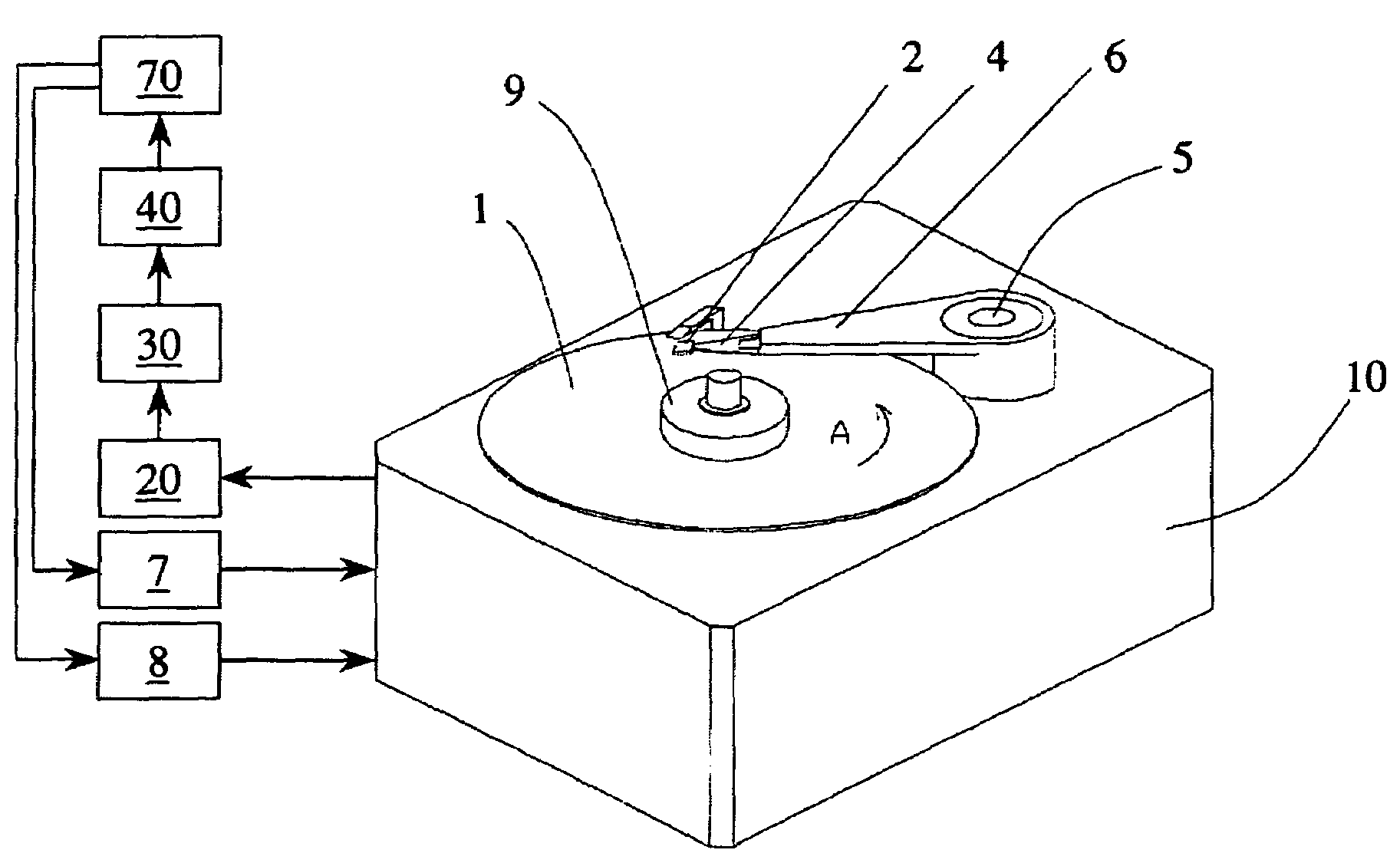
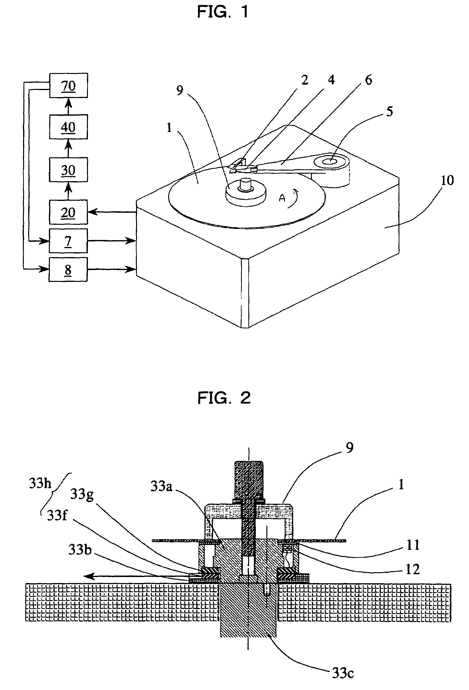
[0056]FIG. 1 is a block diagram showing a contact inspection device in Embodiment 1 of the present invention. Portions corresponding to those in the conventional art shown in FIGS. 12 to 14 are indicated by the same reference numerals, and will not be described in detail.

[0057]In FIG. 1, reference numeral 1 denotes a magnetic disk; reference numeral 2 a slider; reference numeral 4 a suspension; reference numeral 5 a voice coil motor; reference numeral 6 an arm; reference numeral 7 a spindle drive circuit; reference numeral 8 an actuator drive circuit; and reference numeral 9 a disk clamp. Reference numerals 10 denote a frame. The magnetic disk 1 is fixed on a spindle (not shown) in the frame 10 by the disk clamp 9. Reference numerals 20 denote a wide-band amplifier; reference numerals 30 a filter circuit; reference numerals 40 an effective value computation circuit provided as an effective v...

embodiment 2

[0073]FIG. 8 shows a block diagram of a contact inspection device in Embodiment 2 of the present invention. The contact inspection device shown in FIG. 8 is basically the same as the contact inspection device of Embodiment 1 shown in FIG. 1. In the contact inspection device shown in FIG. 8, however, an AE sensor 12b is also fixed on the arm 6 side. When the arm 6 is turned, the suspension 4 is lifted to a ramp block 13 or moves down from the ramp block 13 to directly unload the slider 2 from the magnetic disk 1 or directly load the slider 2 onto the magnetic disk 1. In FIG. 8, reference character 12b denotes an AE sensor fixed by bonding to the arm 6; reference character 20b a wide-band amplifier which amplifies a signal from the AE sensor 12b; reference character 30b a filter circuit for filtering a signal from the wide-band amplifier 20b; and reference character 40b an effective value computation circuit provided as an effective value computation device for computing the effective...


PUM

PropertyMeasurementUnit
voltageaaaaaaaaaa
thicknessaaaaaaaaaa
frequencyaaaaaaaaaa

Abstract

A contact inspection method and device in which a detection element which produces a detection output according to vibration of a rotating body is mounted on the rotating body to detect contact of an object with the rotating body, more particularly a method and device suitable for evaluating mechanical characteristics of a rotating magnetic disk (1) and a slider (2) in a magnetic disk device are provided. A detection element (12) which produces a detection output according to vibration is mounted on a rotating body (1). The detection output is transmitted to a stationary portion through a rotary transformer (33h). The rotating body (1) rotates based on the transmitted detection output. The rotary transformer has a sufficient impedance with which the detection element obtains a predetermined output in a portion of an effective sensitivity band of the detection element.

Description

CLAIM OF PRIORITY[0001]This application claims priority under 35 USC 371 to International Application No. PCT / JP2004 / 015911, filed on Oct. 27, 2004, which claims priority to Japanese Patent Application No. 2003-379743, filed on Nov. 10, 2003, each of which is incorporated by reference in its entirety.TECHNICAL FIELD[0002]The present invention relates to a contact inspection method and device in which a detection element which produces a detection output according to vibration of a rotating body is provided on the rotating body to detect contact of an object with the rotating body. More particularly, the present invention relates to a contact inspection method and device suitable for evaluating mechanical characteristics and tribological characteristics of a magnetic disk which is a recording medium in a magnetic disk device and a slider on which a magnetic head is mounted.BACKGROUND ART[0003]A magnetic disk device for magnetically recording and reproducing information is a high-prec...

Claims


Application Information

Patent Timeline
Patent Type & Authority Patents(United States)
IPC IPC(8): G01N29/07G11B5/455G11B21/21
CPCG11B5/455
Inventor NAKAKITA, MASARU
Owner PANASONIC CORP
Why Eureka
Try Eureka