
Refueling assembly having a check valve receptacle and a replaceable fuel receiver for bottom-filled fuel tanks

a fuel receiver and check valve technology, applied in the direction of valve housings, liquid handling, packaged goods types, etc., can solve the problems of nozzle leakage, receiver wear and tear rather quickly, idle time and non-productive, etc., to facilitate replacement of worn fuel receivers.

Active Publication Date: 2009-09-22
MACKEY DEAN E +1
View PDF8 Cites 13 Cited by
  • Summary
  • Abstract
  • Description
  • Claims
  • Application Information

AI Technical Summary

Benefits of technology

Facilitates the replacement of worn fuel receivers without tank drainage, reducing maintenance time, minimizing fuel leakage, and enhancing safety and security by preventing fuel spray and theft.

Problems solved by technology

Time spent for maintenance and refueling is time that is idle and non-productive.
A significant problem associated with conventional fuel receivers is that the receivers tend to wear rather rapidly.
When a receiver is worn, it causes the nozzle to leak during the refueling operation.
When the leakage becomes serious, the fuel receiver must be replaced.
Unfortunately, it is nearly impossible to empty the tank during operation of the equipment, as the tank will most likely not run dry near refueling equipment.

Method used


Image

  • Refueling assembly having a check valve receptacle and a replaceable fuel receiver for bottom-filled fuel tanks
  • Refueling assembly having a check valve receptacle and a replaceable fuel receiver for bottom-filled fuel tanks
  • Refueling assembly having a check valve receptacle and a replaceable fuel receiver for bottom-filled fuel tanks

Examples


Embodiment Construction

[0043]The fuel receiver and check valve assembly, as well as the check valve drain insert, will now be described in detail with reference to the attached drawing figures.

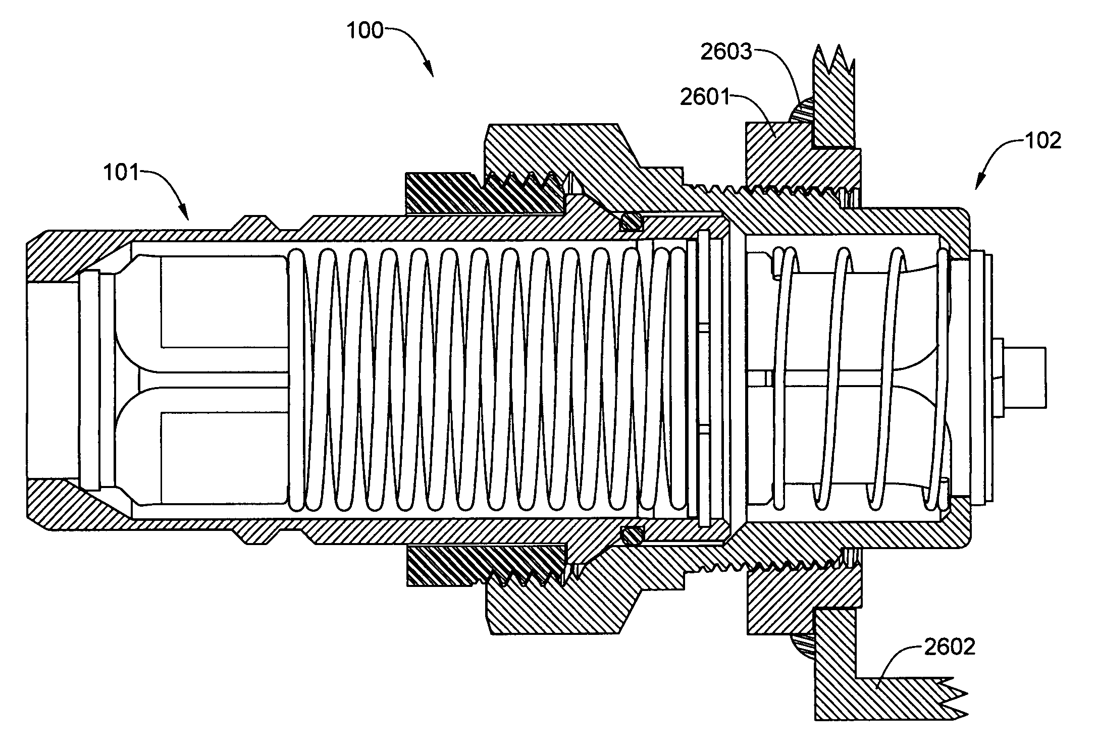
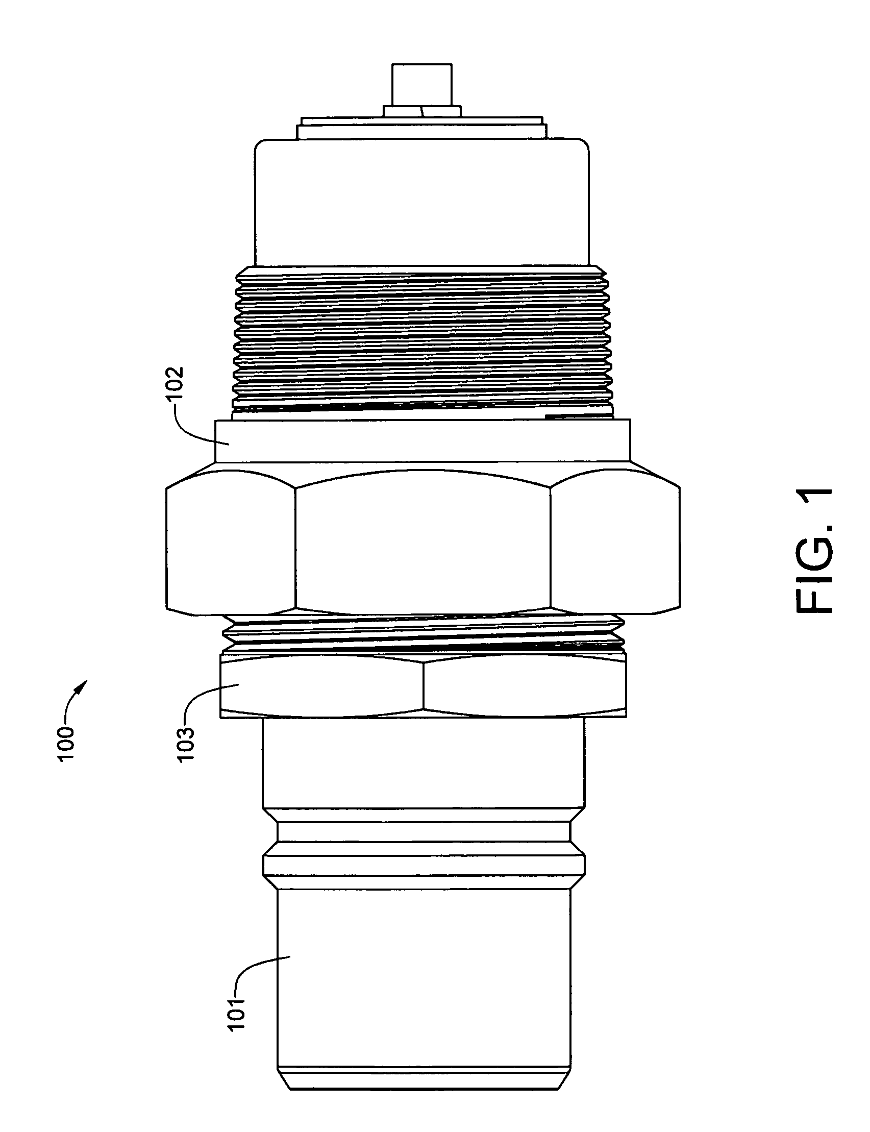
[0044]Referring now to the complete fuel receiver and check valve assembly 100 of FIG. 1, the fuel receiver 101 has been secured within the check valve 102 with an annular securing nut 103.

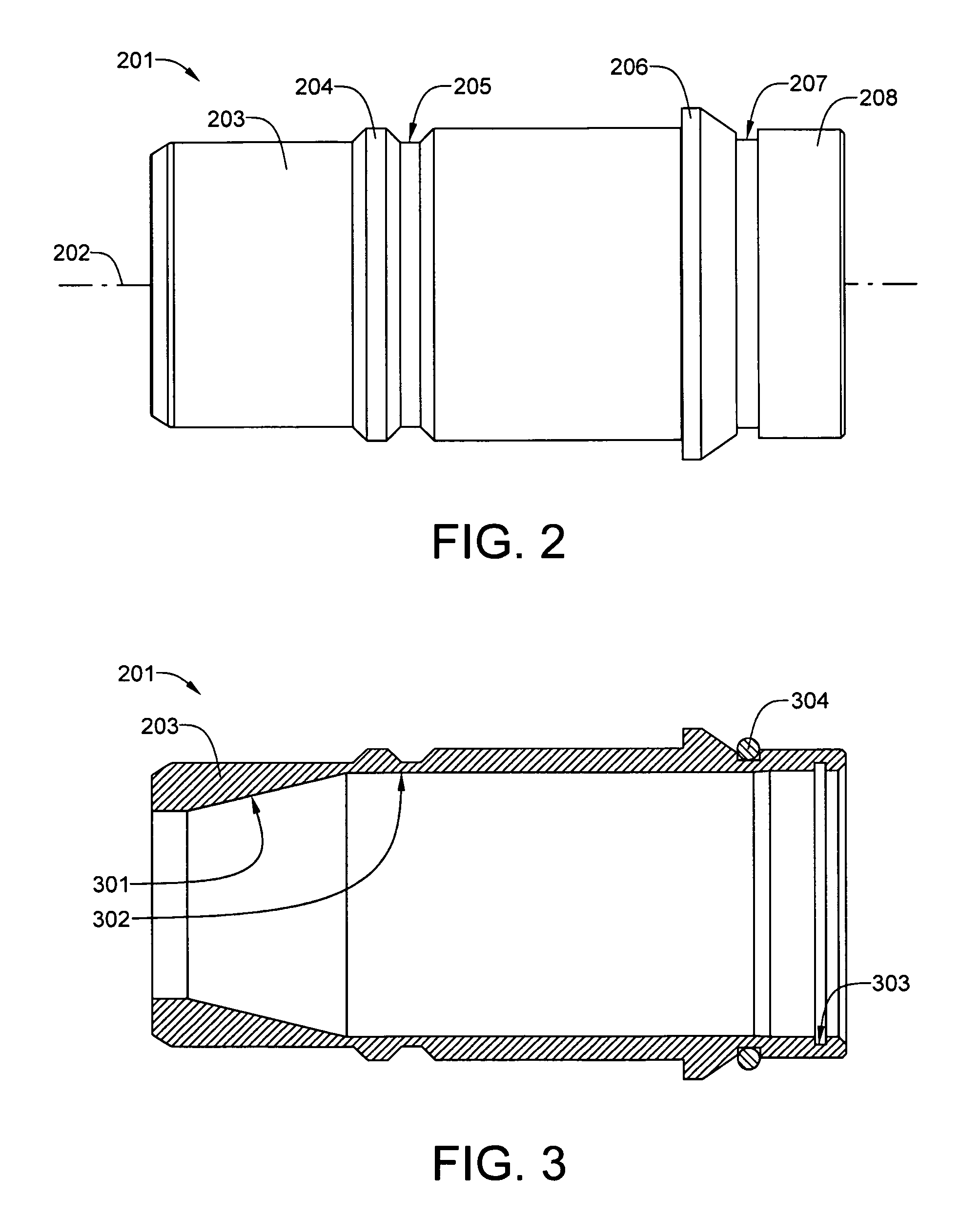
[0045]Referring now to FIG. 2, the fuel receiver body 201 is radially symmetrical about a central axis 202, and has a cylindrical male coupler portion 203 that is equipped with a tapered annular ridge 204, that is followed by a tapered annular groove 205. A high-flow filler nozzle having a cylindrical female coupler, engages and releaseably locks on to the cylindrical male coupler 203. As previously mentioned, such a nozzle is disclosed in U.S. Pat. No. 4,919,174 to Warland. The fuel receiver body 201 also has an annular shoulder 206 and an O-ring groove 207 near an outlet end 208. The annular securing nut 103 seen in FIG. 1 bears...


PUM

PropertyMeasurementUnit
volumeaaaaaaaaaa
pressureaaaaaaaaaa
timeaaaaaaaaaa

Abstract

A fuel receiver assembly, that permits replacement of a worn fuel receiver without draining the fuel tank, includes a check valve receptacle having a male-pipe-threaded nipple which engages the female-threaded pipe coupling of the fuel tank. The check valve receptacle has a spring-biased, normally closed check valve that prevents fuel from escaping from the fuel tank. Fuel pressure from the refueling pump opens the normally-closed check valve. The check valve receptacle is designed to be a relatively permanent installation in the fuel tank, having ultra-low-wear components. The check valve receptacle also has a female-threaded socket that is coaxial with the male-pipe-threaded nipple. A specially-designed male-threaded fuel receiver engages the female-threaded socket. Sealing between the check valve receptacle and the replaceable fuel receiver is accomplished by an O-ring seal installed on the fuel receiver.

Description

[0001]This application has a priority date based on Provisional Patent Application No. 60 / 554,434, which has a filing date of Mar. 18, 2004.BACKGROUND OF THE INVENTION[0002]1. Field of the Invention[0003]This invention relates generally to refueling systems for high-volume bottom-filled tanks on industrial vehicles and, more specifically, to hose-to-tank connectors which incorporate a fuel receiver and a check valve.[0004]2. Description of the Prior Art[0005]Industrial vehicles, such as ore-hauling trucks used in open pit mines, typically have fuel capacities of several hundred gallons. Time spent for maintenance and refueling is time that is idle and non-productive. Because the idling of equipment usually carries with it the idling of workers, it is in the best interest of the owner of such equipment to minimize maintenance and refueling time, particularly if the minimization can be achieved with no adverse effect on the equipment.[0006]Bottom-filled fuel tanks typically have a cou...

Claims


Application Information

Patent Timeline
Patent Type & Authority Patents(United States)
IPC IPC(8): B65B1/04
CPCB60K15/04F16K15/026F16K27/0209B60Y2200/14Y10T137/88046Y10T137/88054Y10T137/7842Y10T137/7846
Inventor MACKEY, DEAN E.JENSEN, KENNETH V.
Owner MACKEY DEAN E
Learn More