
Device and method for manufacturing sausages

a manufacturing method and device technology, applied in the field of devices and methods for the manufacture of sausages, can solve the problems of insufficient strength of sausage casings and sausage skein tears, and achieve the effects of simple device and fast manufacturing method, increased stress, and reduced production costs

Active Publication Date: 2009-09-22
ALBERT HANDTMANN MASCHFABRICK
View PDF11 Cites 4 Cited by
  • Summary
  • Abstract
  • Description
  • Claims
  • Application Information

AI Technical Summary

Benefits of technology

The present disclosure provides a device and method for manufacturing sausages that allows for a sausage casing to be more highly stressed. The sausage casing is extruded onto the filling tube and solidified, which makes it easier to manufacture a sausage casing that can be more highly stressed. The device also includes a lubricating device to prevent the sausage casing from adhering to the filling tube and tearing. The method also allows for easy separation of the sausage casing from the paste mass without damaging it. The device and method provide a simple and fast way to manufacture sausages.

Problems solved by technology

However, since the solidification process takes a certain time, typically 1 to 2 seconds until the casing can be stressed, constricting the sausage skein directly following the coextrusion head presents a problem, for example, in order to initiate a twisting-off process.
The sausage casing is not sufficiently strong for this, so that the sausage skein tears.

Method used


Image

  • Device and method for manufacturing sausages
  • Device and method for manufacturing sausages
  • Device and method for manufacturing sausages

Examples


first embodiment

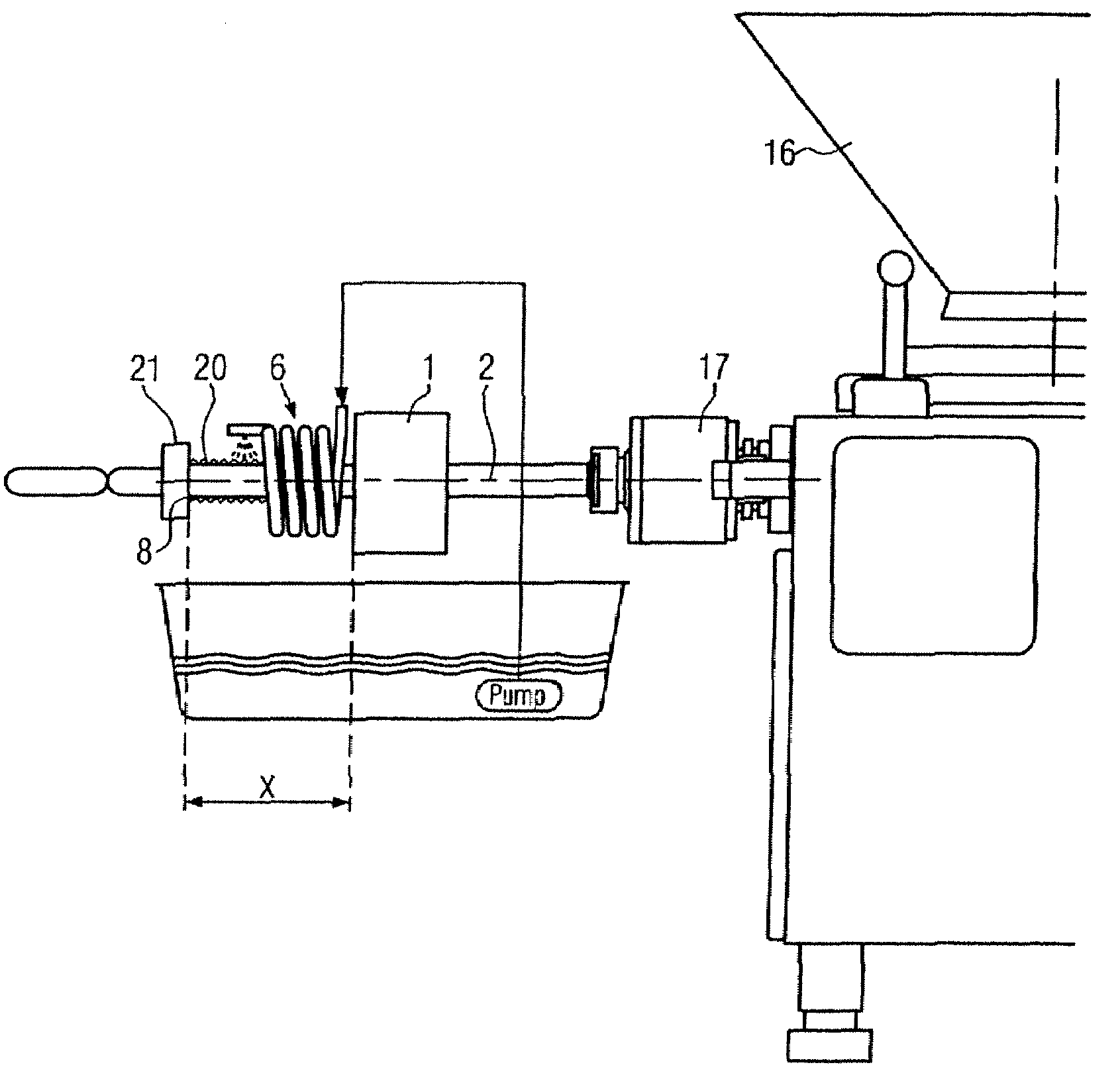
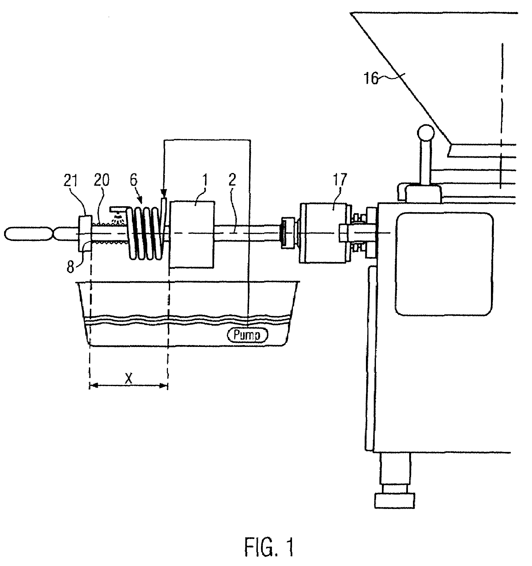
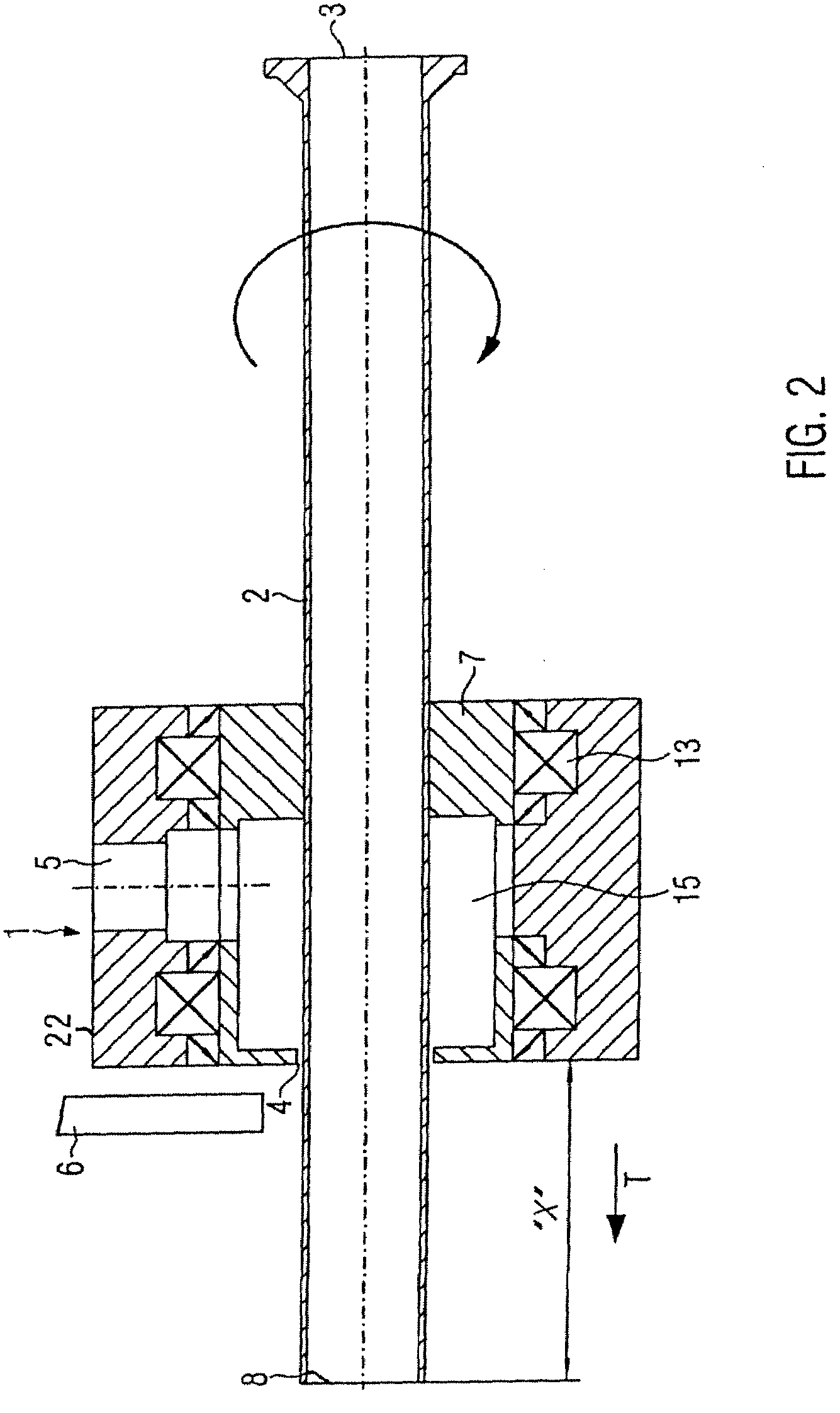
[0025]FIG. 2 illustrates a cross-section through a first embodiment according to the present disclosure. As emerges from FIG. 2, the coextrusion head 1 comprises a housing 22, in which the extrusion die 7 is pivotably supported by appropriate bearings 13 for the ejection of casing material. The housing 22 has a feed 5 for the casing mass material. The extrusion die 7 comprises a die cavity 15 through which the casing material can be extruded via the annular gap 4 onto the filling tube 2. The filling tube 2 extends through the extrusion die 7. Together with the extrusion die, the filling tube 2 is pivotably supported about the longitudinal axis of the filling tube, as indicated by the arrow in FIG. 2, and can be rotated for a parting-off process for parting off a produced sausage skein. The coextrusion head 1 here has a filling tube 2 extended beyond the annular gap 4. The filling tube 2 protrudes by a distance X beyond the annular gap 4. The distance X is preferably 10 to 200 mm lon...

second embodiment

[0027]FIG. 3 illustrates a cross-section through a second embodiment according to the present disclosure. If the coefficient of sliding friction between the filling tube and the ejected casing material or the sausage casing to be manufactured is to be minimize, then in addition a lubricant, such as for example water, can be added. The embodiment illustrated in FIG. 3 corresponds to the embodiment illustrated in FIG. 2 with the exception that here also a lubricating device is provided for feeding a lubricant. The lubricating device comprises a feed 9 for the lubricant. The feed 9 here is formed as a channel in the filling tube 2. In particular the channel here runs in an annular shape in the wall of the filling tube. In the region of the annular gap 4 a further annular gap 10 is arranged here around the outer surface of the filling tube 2. For this, the filling tube 2 in the region behind the further annular gap 10 has a smaller diameter than the filling tube 2 in a region in front o...


PUM


Abstract

A device and a method for the manufacture of sausages from paste mass, in particular sausage meat, with a coextrusion head for coextruding the paste mass and a sausage casing, wherein the coextrusion head comprises a filling tube for the ejection of the paste mass as well as an extrusion die assigned to the filling tube with an extrusion gap for ejecting the easing material. In order to produce strong sausage casings, the filling tube protrudes by a distance X beyond the annular gap so that the casing material is extruded through the annular gap onto the filling tube and solidifies along the filling tube.

Description

CROSS-REFERENCE TO RELATED APPLICATION[0001]The present application claims the benefit of priority of European Patent Application No. 07 014 354.0, filed Jul. 20, 2007. The entire text of the priority application is incorporated herein by reference in its entirety.FIELD OF THE DISCLOSURE[0002]The present disclosure relates to a device and a method for the manufacture of sausages, and more particularly, to a coextrusion head and die for coextruding sausage paste mass and sausage casing.BACKGROUND[0003]Devices and methods of this nature are already known from EP 1 371 293. Here a sausage casing film is pulled over a paste mass (sausage meat) and then following the coextrusion process the produced sausage skein is portioned off. A coextrusion head of this nature is for example illustrated in the present FIG. 5. The sausage casing mass is applied to the paste mass fed through the filling tube 2 via the annular gap 4 by an extrusion die 7. After the coextrusion the sausage casing, which ...

Claims


Application Information

Patent Timeline
Patent Type & Authority Patents(United States)
IPC IPC(8): A22C11/00
CPCA22C11/0209A22C13/0003A22C2013/0023
Inventor BACHTLE, MANFREDREUTTER, SIEGFRIEDSCHLIESSER, MARKUS
Owner ALBERT HANDTMANN MASCHFABRICK
Learn More