Epicyclic gear train integral sun gear coupling design

a technology of sun gear and gear train, applied in the direction of coupling, gear, machine/engine, etc., can solve the problems of increasing the stress on the gear components, causing the gear components to be more susceptible to breakage and wear, and the conditions are often less than ideal

Active Publication Date: 2009-09-22
RTX CORP
View PDF5 Cites 387 Cited by
  • Summary
  • Abstract
  • Description
  • Claims
  • Application Information

AI Technical Summary

Problems solved by technology

The forces and torque transferred through a planetary gear train place tremendous stresses on the gear train components, making them susceptible to breakage and wear, even under ideal conditions.
In practice, conditions are often less than ideal and place additional stresses on the gear components.
Perfect or ideal coaxial alignment, however, is rare due to numerous factors including imbalances in rotating hardware, manufacturing imperfections, and transient flexure of shafts and support frames due to aircraft maneuvers.
The imposed forces and moments accelerate gear component wear and increase the likelihood of component failure in service.
Thus, accelerated component wear necessitates frequent inspections and part replacements which can render the engine and aircraft uneconomical to operate.
However, increased size offsets the compactness that makes planetary gear trains appealing for use in aircraft engines, and the corresponding weight increase is similarly undesirable.
The use of high strength materials and wear resistant coatings can also be beneficial, but escalates the cost of the gear train and therefore reduces its desirability.
Many prior art couplings, however, contain multiple parts which require lubrication and are themselves susceptible to wear.
Prior art couplings may also lack adequate rigidity and strength, with respect to torsion about a longitudinal axis, to be useful in high torque applications.
However the motion that occurs between the contacting spline teeth in a splined connection creates friction which is highly variable and causes the flexibility of such a connection to also be variable.

Method used


Image

  • Epicyclic gear train integral sun gear coupling design
  • Epicyclic gear train integral sun gear coupling design
  • Epicyclic gear train integral sun gear coupling design

Examples


Embodiment Construction

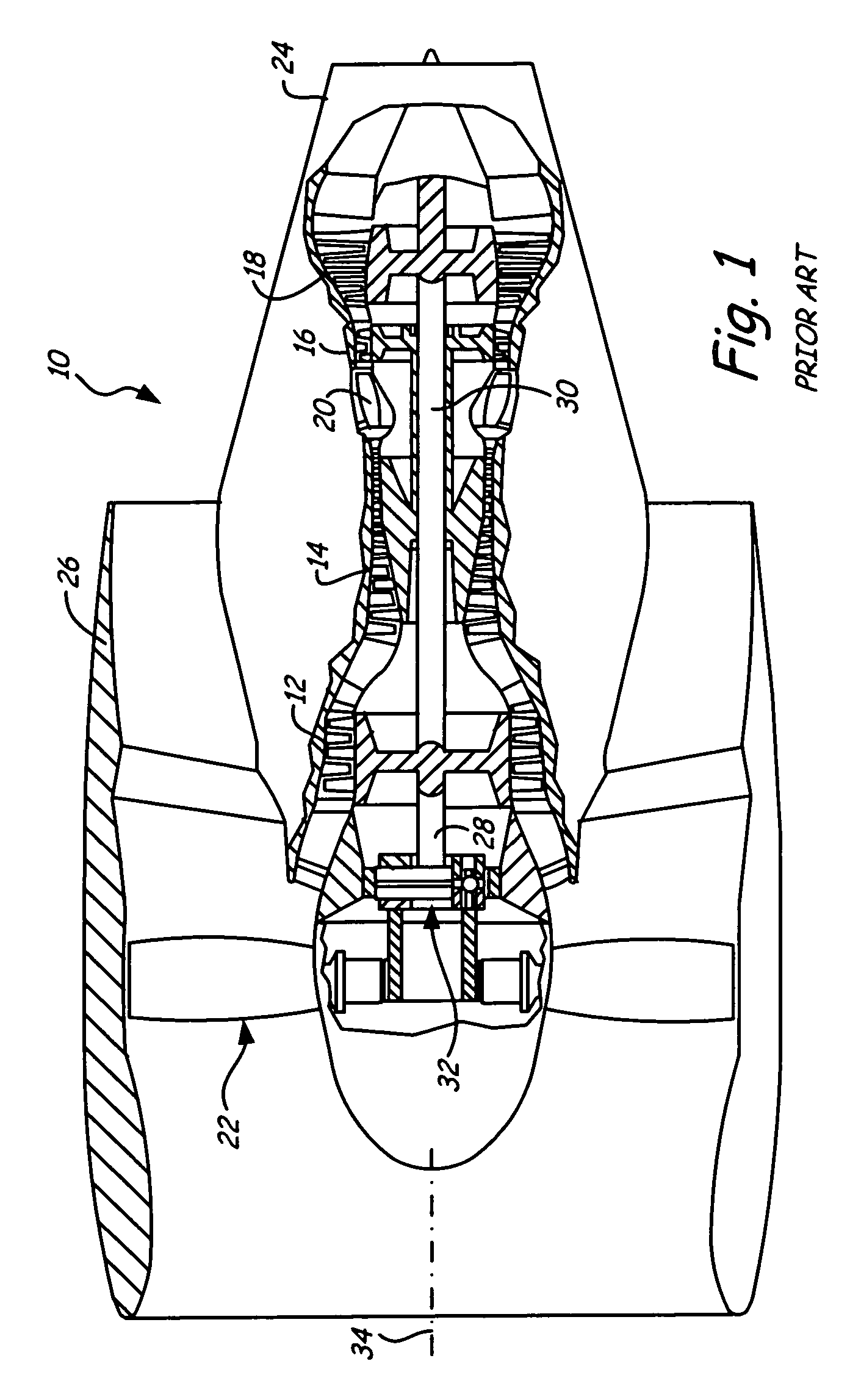
[0011]FIG. 1 shows a typical turbine engine 10 known in the art, which includes as its principal components one or more compressors 12, 14, one or more turbines 16, 18 for powering compressors 12, 14, combustion chamber 20, fan 22, primary exhaust 24 and fan exhaust nozzle 26. A power train such as shafts 28, 30 extends from each turbine 16, 18 to drive the corresponding compressor 12, 14. The rotary motion of one of compressors 12, 14 is conveyed to fan 22 by way of planetary gear train 32. Planetary gear train 32 reduces the rotational speed of a compressor to a speed more suitable for the efficient operation of fan 22. The principal engine components are ideally concentric with central longitudinal axis 34.

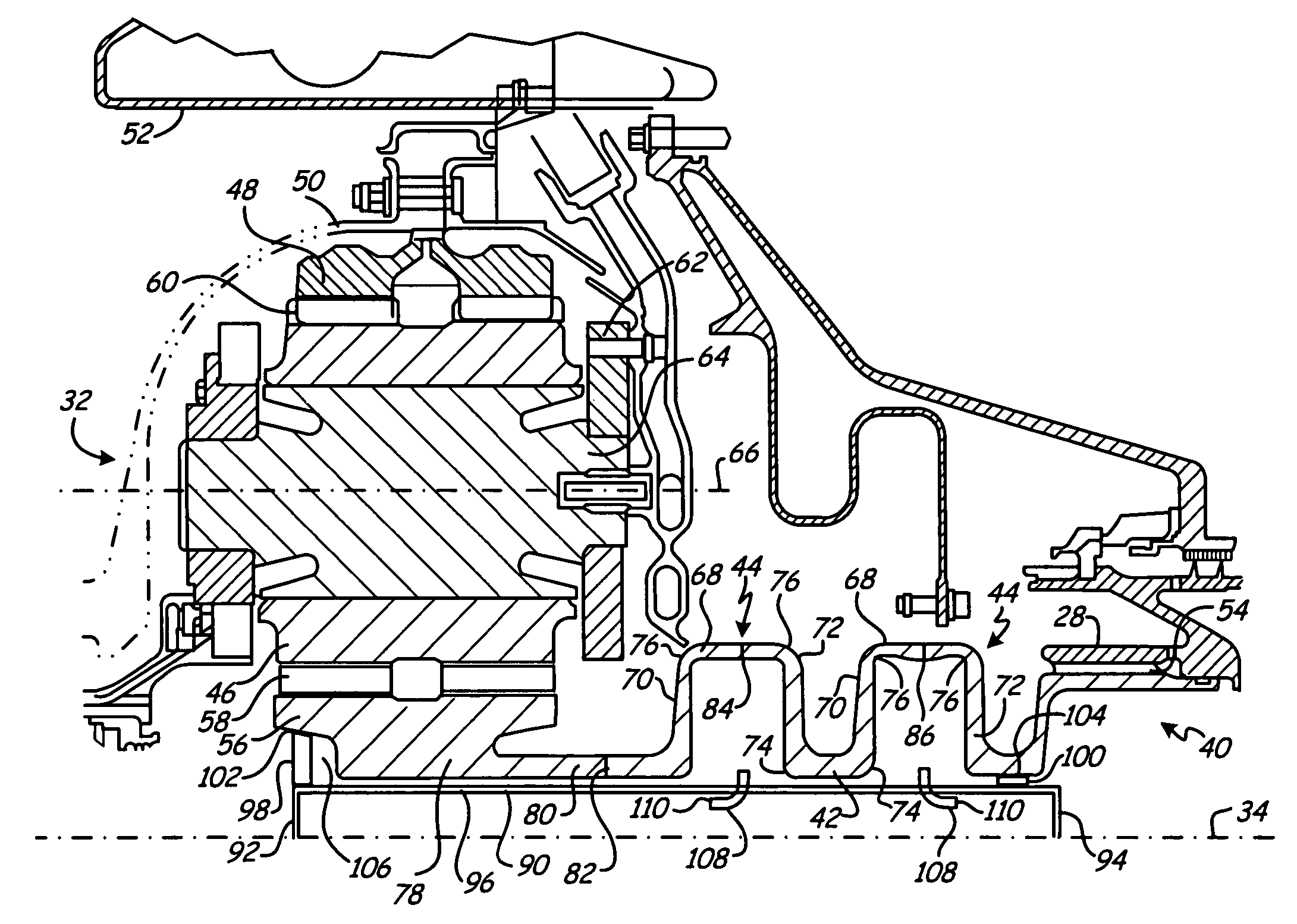
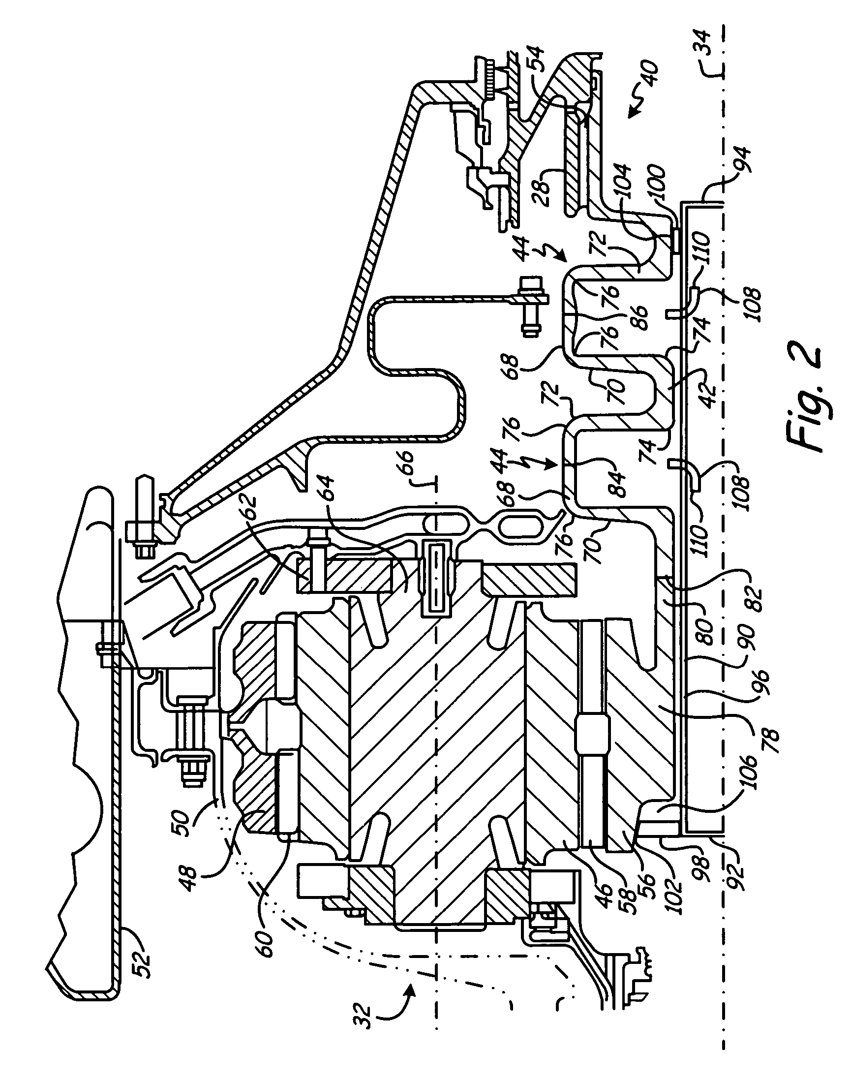
[0012]FIG. 2 is a cross-sectional elevation view of an integral coupling system 40 for planetary gear system 32 of FIG. 1, and its relationship to engine 10. Integral coupling system 40 comprises inflexible spindle 42 and at least one undulant flexible section 44 which rotate a...


PUM

PropertyMeasurementUnit
flexibleaaaaaaaaaa
outer radius Raaaaaaaaaaa
outer radius thickness Taaaaaaaaaaa

Abstract

A coupling system for connecting a sun gear to a shaft within a planetary gear train, includes a sun gear coupling connecting the sun gear to the shaft. The sun gear coupling has at least one undulant flexible section joined to an inflexible spindle for accommodating misalignment between the sun gear and the shaft. The flexible section comprises a cylindrical ring having a diameter greater than the diameter of the spindle, and joined to the spindle by two longitudinally spaced apart diaphragms. The juncture between the diaphragms, the ring, and the spindle is curved in cross section on an outer side to improve flexibility and minimize stress concentrations, and the inner sides of the diaphragms are straight edges which result in a non-symmetric contour of the diaphragm walls.

Description

BACKGROUND OF THE INVENTION[0001]This invention relates to planetary gear trains. More particularly, the invention relates to a coupling system for flexibly connecting a sun gear to a rotating shaft so that the reliability and durability of the gear system components are improved. The invention is useful in aircraft engines where reliability, durability and simplicity are highly desirable.[0002]Planetary gear trains are mechanical structures for reducing or increasing the rotational speed between two rotating shafts. The compactness of planetary gear trains makes them appealing for use in aircraft engines where space is at a premium.[0003]The forces and torque transferred through a planetary gear train place tremendous stresses on the gear train components, making them susceptible to breakage and wear, even under ideal conditions. In practice, conditions are often less than ideal and place additional stresses on the gear components. For example, the longitudinal axes of a sun gear, ...

Claims


Application Information

Patent Timeline
Patent Type & Authority Patents(United States)
IPC IPC(8): F16H57/08
CPCF16D3/72F16H1/2845Y10T29/49968Y10T29/49995Y10T29/49464F02C7/36F05D2260/40311Y02T50/60F16H3/44F16H3/00F16H3/66
Inventor DUONG, LOCMCCUNE, MICHAEL E.DOBEK, JR., LOUIS J.
Owner RTX CORP
Why Eureka
Try Eureka