
Weighing device, especially load cell for a combination scale

Active Publication Date: 2009-09-22
WIPOTEC WIEGE UND POSITIONIERSYSTEME GMBH
View PDF10 Cites 5 Cited by
  • Summary
  • Abstract
  • Description
  • Claims
  • Application Information

AI Technical Summary

Benefits of technology

[0010]The invention starts from the knowledge that for weighing equipment, in which the partial weight signals of the individual weighing devices are not determined in analog and calculated by means of an analog computer to form the desired difference or sum signal, but instead in which the analog partial weight signals are first digitized and then the digitized and optionally averaged partial weight signals are added or subtracted, the problem arises that any time delay in the digitizing of the partial weight signals and any time delay in the calculation of digitized values of the partial weight signals leads to measurement error in the determination of the total weight. This has a strong effect in particular in precision measurements by means of fast, dynamic scales, when medium-sized and large masses are moved at high speed during the weighing process over the several weighing belt conveyors of a combination scale.
[0016]According to a preferred embodiment of the invention, the synchronization output is constructed as a separate output, to which the synchronization signal is fed in the form of a digital signal. In other words, the synchronization output should not be realized in the framework of a communications bus on which the synchronization signal is transmitted to the slave weighing device as a software instruction to be decoded. By using a separate synchronization output, to which the synchronization signal is fed exclusively, impermissible time deviations and delays in the transmission of the information concerning the starting time points of the analog / digital conversion processing performed in the master weighing device are prevented.
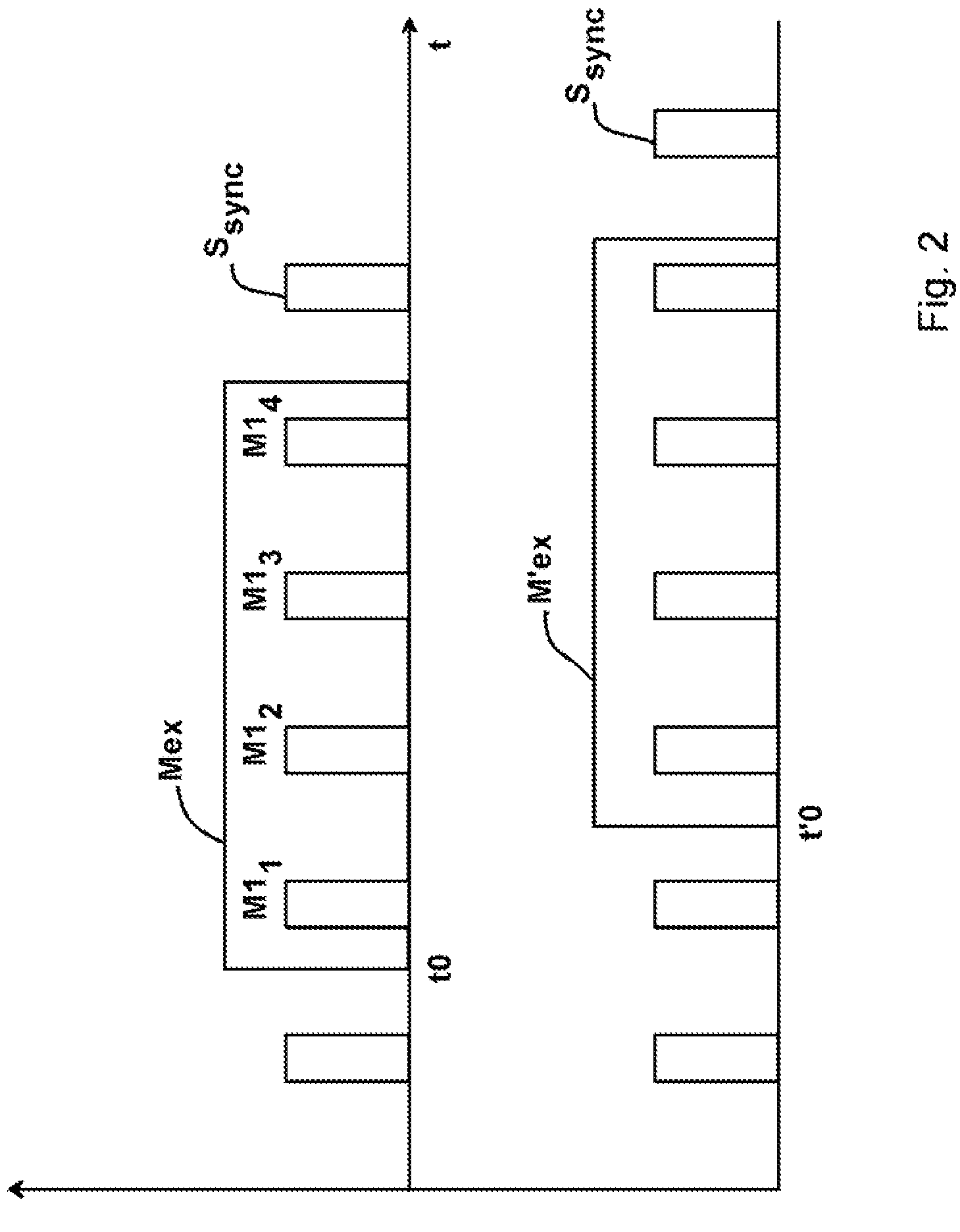
[0027]In this way, the delay between the detection of the starting event in the external measurement process signal and the generation of the starting event as a function of the measurement process signal can be selected so that the slave measurement cell under all circumstances would detect a series of successive sampled values, which are delayed by a number m of sampling time points relative to the sampled values detected by means of the master measurement window of the master weighing device, during the slave measurement window.

Problems solved by technology

In principle, this problem also occurs in weighing equipment with several weighing devices (so-called multi-point weighing equipment), when the product to be weighed is displaced during the measurement value determination of the individual partial weights.
A time offset of the partial weight values determined by the individual weighing devices can result as a constant delay, for example, due to filter propagation times or transient characteristics of the mechanical and electrical components of the weighing devices including their control behavior and also due to certain constant propagation times of software processes, and as a random delay or jitter, for example, due to the processing of software processes as a reaction to randomly occurring external events.

Method used


Image

  • Weighing device, especially load cell for a combination scale
  • Weighing device, especially load cell for a combination scale
  • Weighing device, especially load cell for a combination scale

Examples


Embodiment Construction

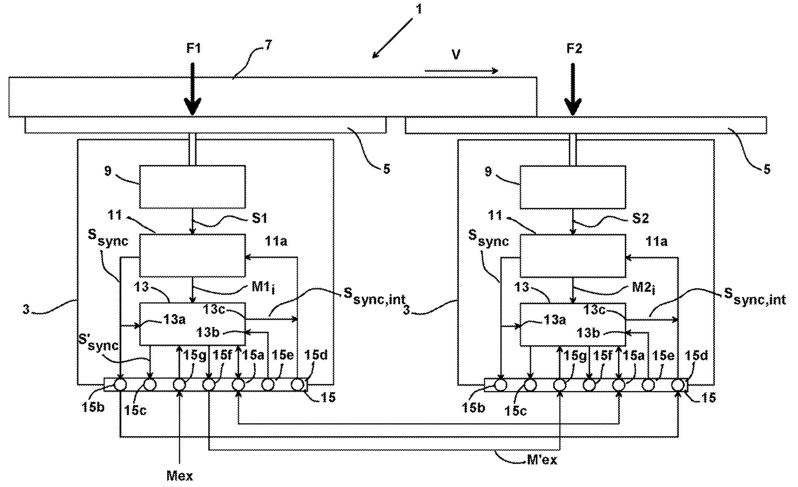
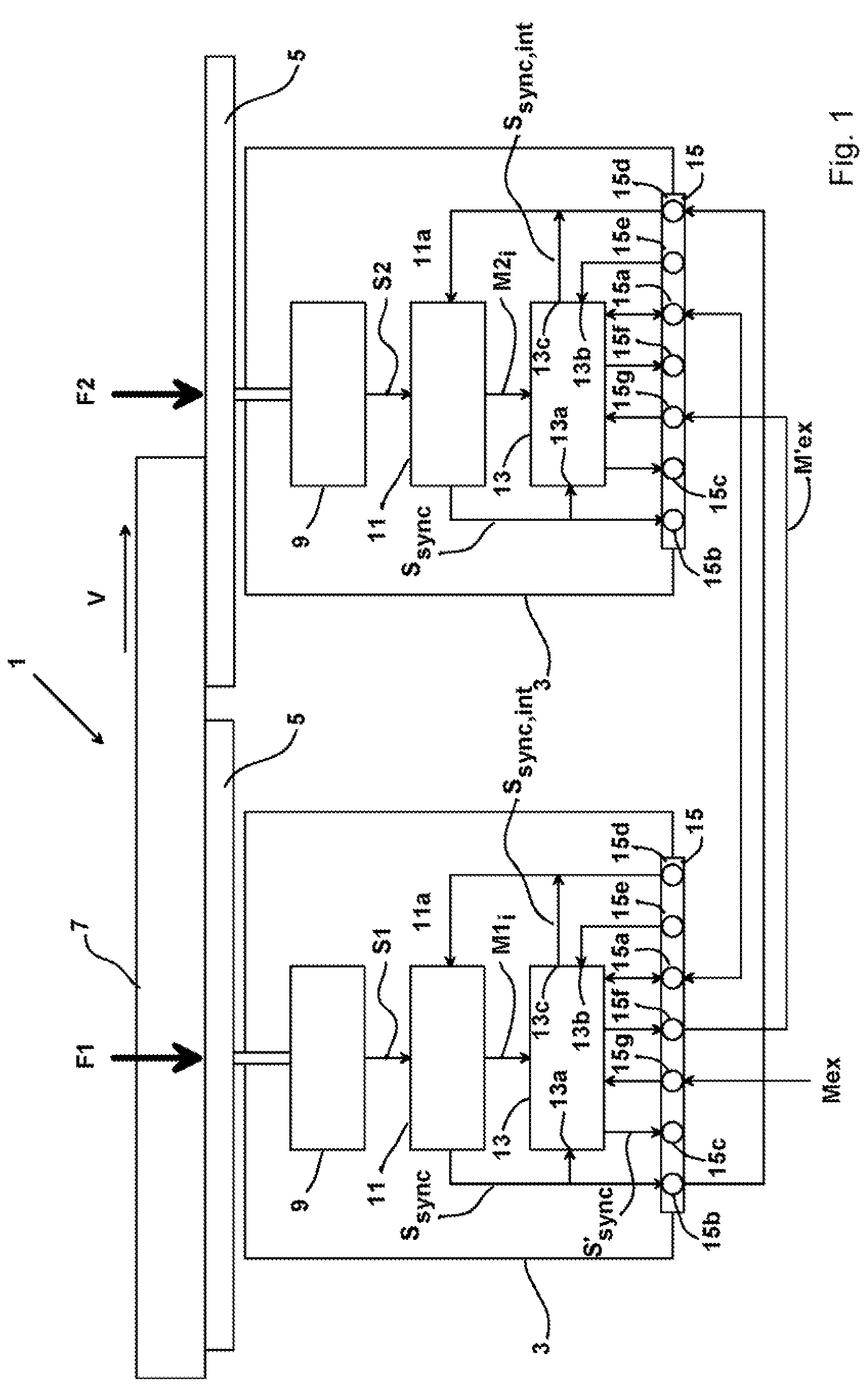
[0036]The weighing equipment 1 shown schematically in FIG. 1 is constricted as a combination scale and comprises two weighing devices, which are constructed as load cells 3 and which each have available a load sensor 5 constructed as a conveyor belt. Basically, however, the principle described with reference to the figures can obviously also be transferred to weighing devices of any kind.

[0037]On the load sensors 5 of the combination scale 1, a product 7 to be weighed can be transported in the direction indicated by the arrow, wherein the weighing equipment should determine the total weight of the product 7. For this purpose, the partial weights F1 and F2 are determined by means of the load cells 3 and combined computationally to form the total weight FG=F1+F2. The partial weights F1 and F2 exerted on the load sensors 5 each act on a force sensor unit or a force sensor 9 of the appropriate load cell 3, respectively.

[0038]Each of the force sensors 9 converts the weight F1, F2 exerted...


PUM


Abstract

A weighing device for a combination scale includes a force-sensing unit for converting a weight acting on a load sensor of the force-sensing unit into an analog electrical signal and an analog / digital converter to which the analog electrical signal is fed and which converts the analog electrical signal into a digital electrical signal. the weighing device further includes a controller for controlling the analog / digital converter and for additional digital processing of the digital values of the digital electrical signal fed to it. The weighing device has a synchronization output which is connected to the controller or to the analog / digital converter and to which a synchronization signal is fed that includes at least the information of the starting time points of the individual conversion processes performed by the analog / digital converter unit for determining a digital value of the digital electrical signal, and / or the weighing device has a synchronization input connected to the controller (13) or the analog / digital converter to which an external synchronization signal can be fed that includes at least the information of one or more desired starting time points for a conversion process to be performed by the analog / digital converter for determining a digital value of the digital electrical signal.

Description

TECHNICAL FIELD OF THE INVENTION[0001]The invention relates to a weighing device, especially a load cell for a combination scale, with a synchronization arrangement by which the measurements by the load cell may be synchronized with measurements provided by one or more additional load cells. In addition, the invention relates to weighing equipment with at least two such weighing devices, especially a combination scale.BACKGROUND OF THE INVENTION[0002]For weighing equipment in which a partial weight is determined by each of several weighing devices and a sum or difference weight is determined from the individual partial weights, as is the case, for example, in combination scales, there is often the demand, as is also the case for weighing equipment with a single weighing device, for fast and also high-precision determination of the partial weights or the sum or difference weight. However, when weighing equipment with a single weighing device, the measurement result can in particular ...

Claims


Application Information

Patent Timeline
IPC IPC(8): G01G19/00
CPCG01G11/046G01G19/4148G01G19/393G01G19/005
Inventor DUPPRE, THEO
Owner WIPOTEC WIEGE UND POSITIONIERSYSTEME GMBH
Learn More