
Method and system for dynamically assigning channels across multiple access elements in a wireless LAN

a wireless lan and access element technology, applied in the field of wireless local area networks, can solve the problems of significant degrading communication performance, physical realizable networks, and inability to ensure that neighboring access elements do not use duplicate channels in denser areas, so as to minimize this effect, maximize user performance, and optimize network performance

Active Publication Date: 2009-09-22
CISCO TECH INC
View PDF20 Cites 57 Cited by
  • Summary
  • Abstract
  • Description
  • Claims
  • Application Information

AI Technical Summary

Benefits of technology

[0013]The advantages of this invention relate to how it incorporates the load and the interference of the network in the channel assignment process and the speed at which it can dynamically update the channel assignments of the participating radios (client remote elements). For example, a highly loaded access element might have priority for a low interference channel over a lightly loaded neighboring access element, since the highly loaded access element requires a channel that will provide optimal network performance.
[0014]In one embodiment, the present invention accounts for interference due to the energy that “spills over” to adjacent channels from the operation of access elements operating on given channels. That is, in one embodiment, the present invention accounts for the contribution of signal measurements on a given channel from the access elements on different physical channels (e.g., first adjacent channels in the 802.11 a protocol, and several adjacent channels in the 802.11 b protocol). Accounting for the interference observed at adjacent channels from operation of the access elements allows for deployment of access elements in denser arrangements, while minimizing interference among access elements due to channel re-use. In 802.11 b WLAN environments, embodiments of the present invention also allow for use of over-lapping channels in the available range of physical channels.
[0015]The present invention does not follow the ISO model of isolating information between the layers of protocols. The centralized Radio Resource Manager has access to information from the physical layer, the MAC layer and the IP layer allowing it to make better decisions on resource allocation and configuration at the physical layer.

Problems solved by technology

When two neighboring access elements use the same channel (or partially spectrally overlapping channels where such is possible), interference occurs that significantly degrades communication performance.
However, certain wireless protocols (e.g., 802.11b) provide for only a small number of spectrally non-overlapping channels assignable to the access elements, depending for reliability of communication more on the ad hoc lack of density of access elements and low levels of activity in a limited region of propagation.
Thus it is impossible to ensure that neighboring access elements do not use duplicate channels in denser, physically realizable networks.
However, such methods of channel selection are made with limited local information and do not take into account the needs of neighboring access elements.
The model does not provide for ready visibility of activities across layers and, particularly, visibility of activities in other than neighboring layers.

Method used


Image

  • Method and system for dynamically assigning channels across multiple access elements in a wireless LAN
  • Method and system for dynamically assigning channels across multiple access elements in a wireless LAN
  • Method and system for dynamically assigning channels across multiple access elements in a wireless LAN

Examples


Embodiment Construction

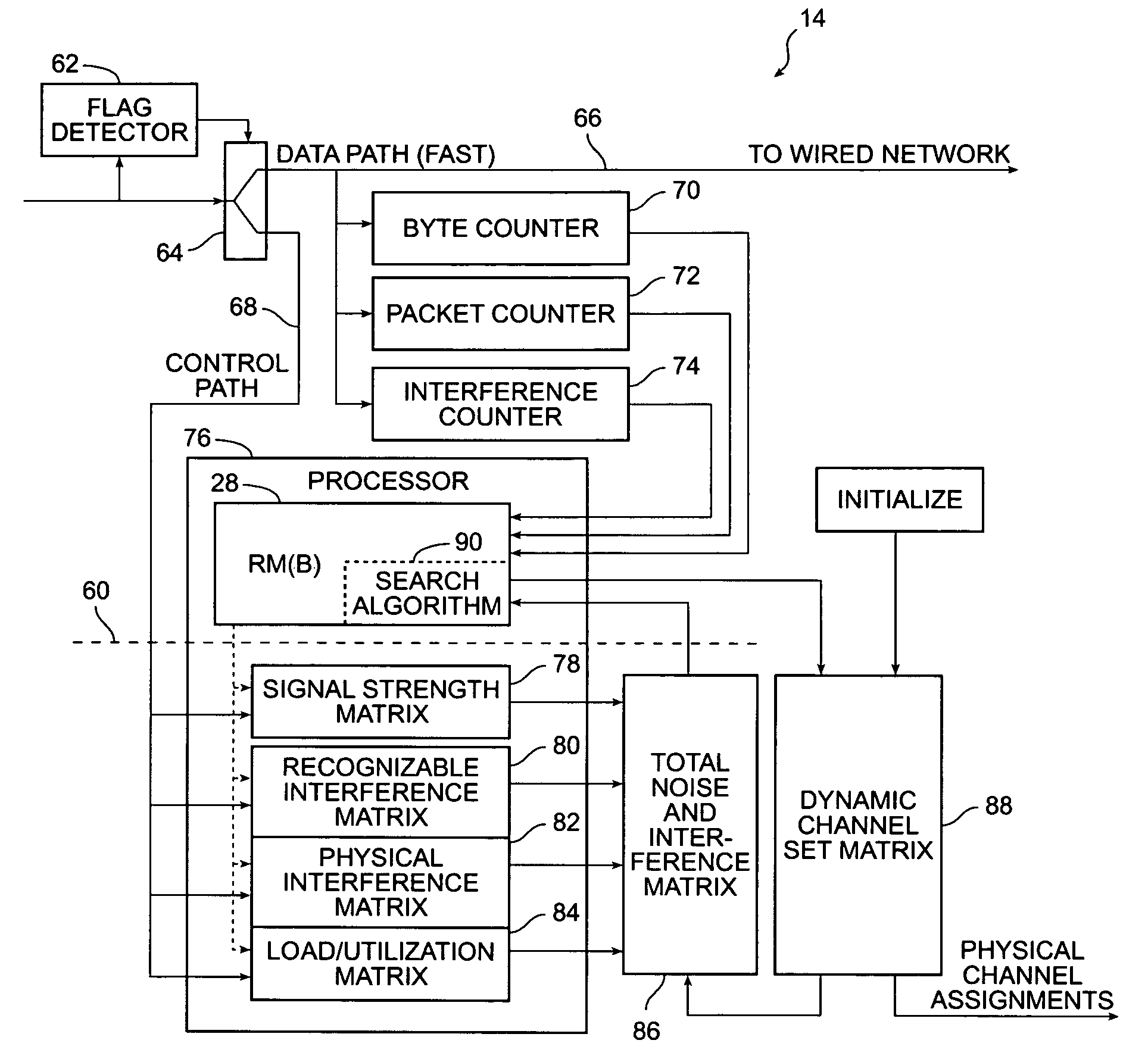
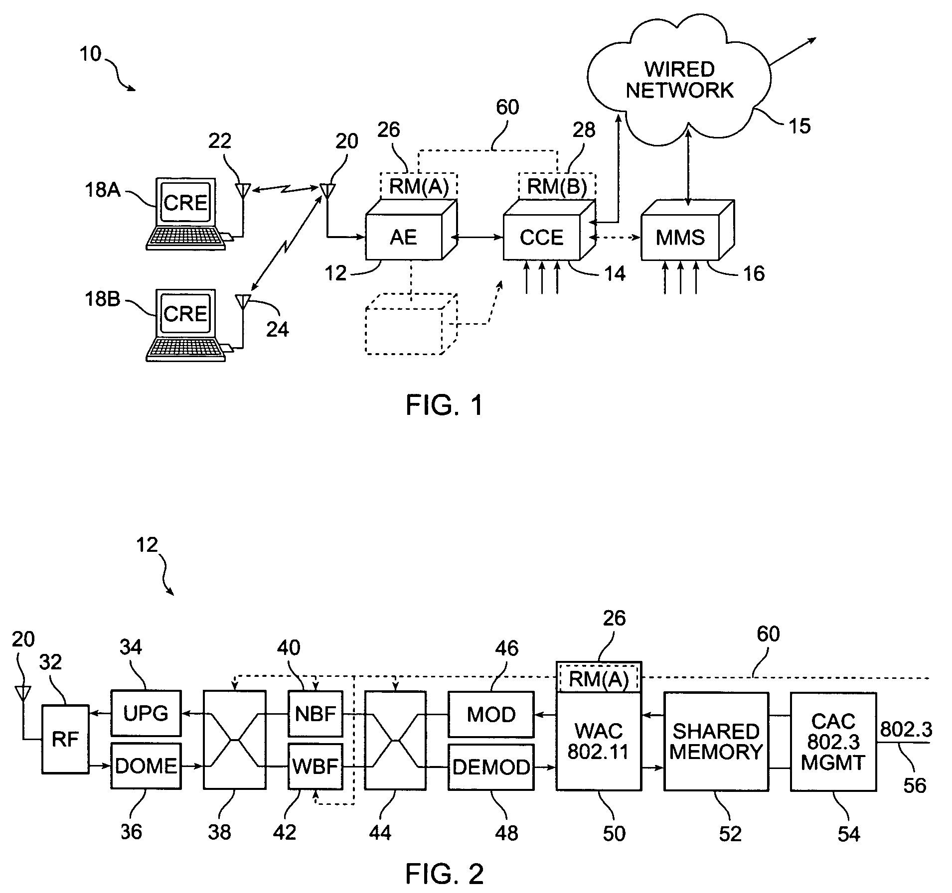
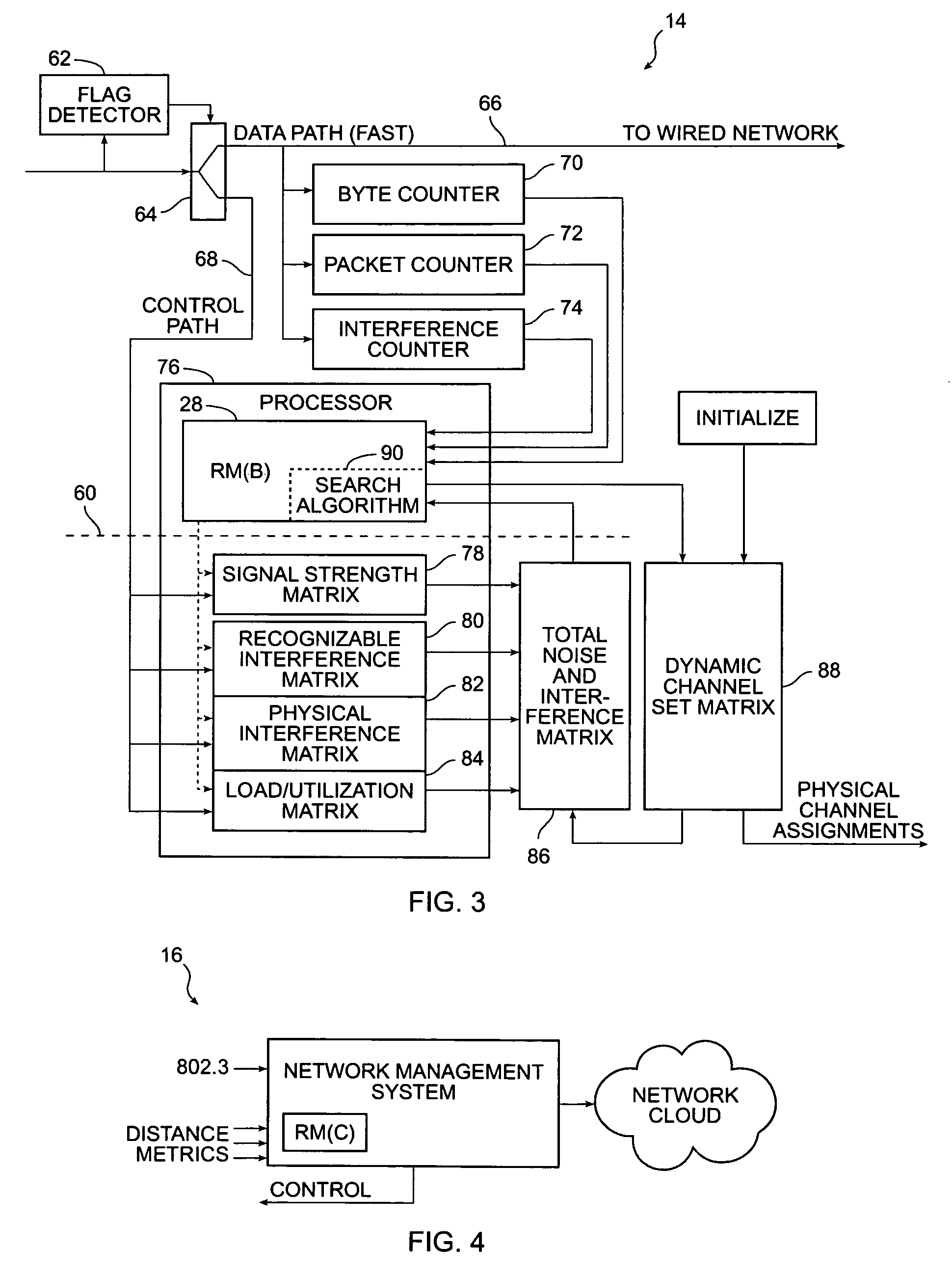
[0021]Reference is made to FIG. 1. A specific embodiment of the invention comprises a wireless communication system 10 which includes an access element 12, a central control element 14, a network management system 16 and one or more client remote elements 18A, 18B in wireless contact on one of a limited number of wireless channels. The access element 12 includes the means to communicate with the client remote elements 18A, 18B using a wireless LAN protocol, usually via conventional antennas 20, 22, 24. The control and network management functionality according to the invention is imbedded in and distributed between the access element 12 and the central control element 14 as Resource Manager (A) module 26 and Resource Manager (B) module 28, as hereinafter explained. Data is communicated to a wired network 15 with the outside world. The network management system 16 is in logical communication with the central control element 14 for control purposes. The Radio Resource Manager (RM [60]...


PUM


Abstract

In a fixed channel wireless network system with a limited number of channels, assignment of the fixed channels between remote client elements and access elements is made systematically according to a set of criteria according for network loading and interference, then channel assignments are dynamically updated according to a priority to maintain optimal network performance with changing conditions of load and interference. The channel utilization problem is addressed at a system level rather than at a local level by treating the system as a three dimensional color mapping problem. All noise is treated as having a source in virtual access elements with an appropriate performance metric. The performance metric is used to select a channel set that minimize chances of interference and maximize user performance. Specifically, there are several parameter matrices which are managed and updated by a central resource management element, namely signal strength between elements, interference, and load. These matrices are used to find the optimal channel assignments for a predetermined limited set of assignable channels. In one implementation, the channel assignment methodology takes into account the interference associated with access elements operating on a selected channel, as well as the interference or energy that spills over (or is otherwise observable) on physical channels adjacent to the selected channel.

Description

CROSS-REFERENCES TO RELATED APPLICATIONS[0001]The present application is a continuation-in-part of U.S. application Ser. No. 10 / 183,704 filed Jun. 25, 2002 now U.S. Pat. No. 7,327,697 and entitled “Method and System for Dynamically Assigning Channels Across Multiple Radios in a Wireless LAN.”STATEMENT AS TO RIGHTS TO INVENTIONS MADE UNDER FEDERALLY SPONSORED RESEARCH OR DEVELOPMENT[0002]NOT APPLICABLEREFERENCE TO A “SEQUENCE LISTING,” A TABLE, OR A COMPUTER PROGRAM LISTING APPENDIX SUBMITTED ON A COMPACT DISK.[0003]NOT APPLICABLEBACKGROUND OF THE INVENTION[0004]This invention relates to wireless Local Area Networks (wireless LANs) and more specifically to the area of dynamic channel assignment for wireless LANs. Wireless protocols, such as the 802.11 family of protocols for WLANs, make use of a finite number of fixed channels. Each channel is a distinct communication path between an access element and a client remote element, such as a mobile station. Each access element must be ass...

Claims


Application Information

Patent Timeline
IPC IPC(8): H04B7/005
CPCH04W72/082H04B17/382H04B17/24H04B17/309H04W72/08H04W72/085H04W84/12H04W72/0486H04B17/318H04W72/52H04W72/54H04W72/541H04W72/542
Inventor FRIDAY, ROBERT J.CALHOUN, PATRICE R.O'HARA, JR., ROBERT B.HILLS, ALEXANDER H.DIETRICH, PAUL F.
Owner CISCO TECH INC
Learn More