Protection shield for disk brake

a protection shield and disk brake technology, applied in the direction of braking discs, fluid-actuated brakes, brake drums, etc., can solve the problems of uneven wear, negative effect of disk brakes, changes in friction, etc., and achieve the effect of rapid increase in the cooling of the brake disk

Inactive Publication Date: 2009-09-29
VOLVO LASTVAGNAR AB
View PDF15 Cites 14 Cited by
  • Summary
  • Abstract
  • Description
  • Claims
  • Application Information

AI Technical Summary

Benefits of technology

[0007]One object of the invention is to produce a protection device that meets the requirements indicated above and at the same time is simple, reliable and affordable.
[0008]To this end, a protection device configured according to the teaching of the present invention is characterized in that the protection device comprises at least one protection means (protector or shield) which consists at least partly of a material of which the shape is influenced by heat. The protection means has a first end position that effectively prevents (not necessarily absolutely prevents, but precludes at least a sufficient amount to avoid degradation) dirt particles and relative wind from striking the brake disk directly. A second end position allows relative wind to strike the brake disk directly so as to obtain cooling of the brake disk. The first end position occurs when the temperature of the protection means lies below a first temperature and the second end position occurs when the temperature of the protection means exceeds a second temperature. By virtue of this design of the protection device, advantageously simple and effective self-adjusting opening and closing of one or more ventilation openings at the brake disk are obtained.
[0010]In a second advantageous illustrative embodiment of the invention, the protection means changes shape stepwise from the first end position to the second end position. By virtue of this design of the protection device, a rapid increase in the cooling of the brake disk is obtained when a given temperature has been reached.
[0013]In a fifth advantageous illustrative embodiment of the invention, the heat-influencable material consists at least partly of a bimetal. By virtue of this design of the protection device, a protection shield which opens and closes the air supply for cooling a brake disk is obtained in a simple and inexpensive manner.

Problems solved by technology

The functioning of disk brakes is affected negatively by contamination, which can lead to changes in friction, uneven wear and also corrosion on disks and linings.
The protection plate can be configured so that it covers the brake disk effectively but, when the brake disk is completely covered, cooling is also impaired.
Brakes on vehicles such as heavy-duty trucks, exemplarily configured as disk brakes, are sometimes subjected to very high power dissipation.
In this connection, problems can arise if brake disks do not receive sufficient cooling.
It has been found that the power dissipation is usually quite low at low speed.
In many cases, low speed is due to a poor road standard, for example in the case of transporting lumber on forest roads, the road environment usually being very dirty as well.
It is necessary, however, that such devices cannot be put out of operation, which in turn could lead to impaired braking effect; that is to say, the overall safety of the vehicle being put at risk.
This known solution is complicated and sensitive to contamination, for which reason it is not a realistic possibility for application to heavy-duty trucks, which are expected to cope with service intervals of roughly 50,000 km.
Such a configuration, however, would be a prohibitively expensive solution for a truck which has at least four brake disks.

Method used


Image

  • Protection shield for disk brake
  • Protection shield for disk brake
  • Protection shield for disk brake

Examples


Embodiment Construction

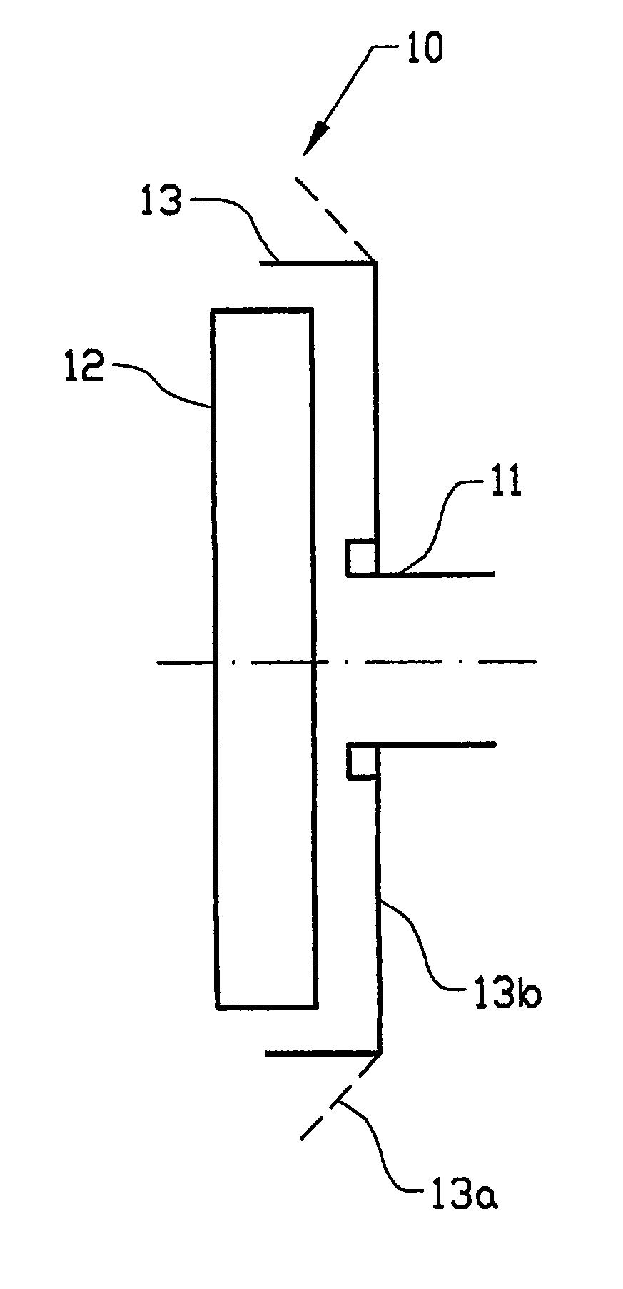
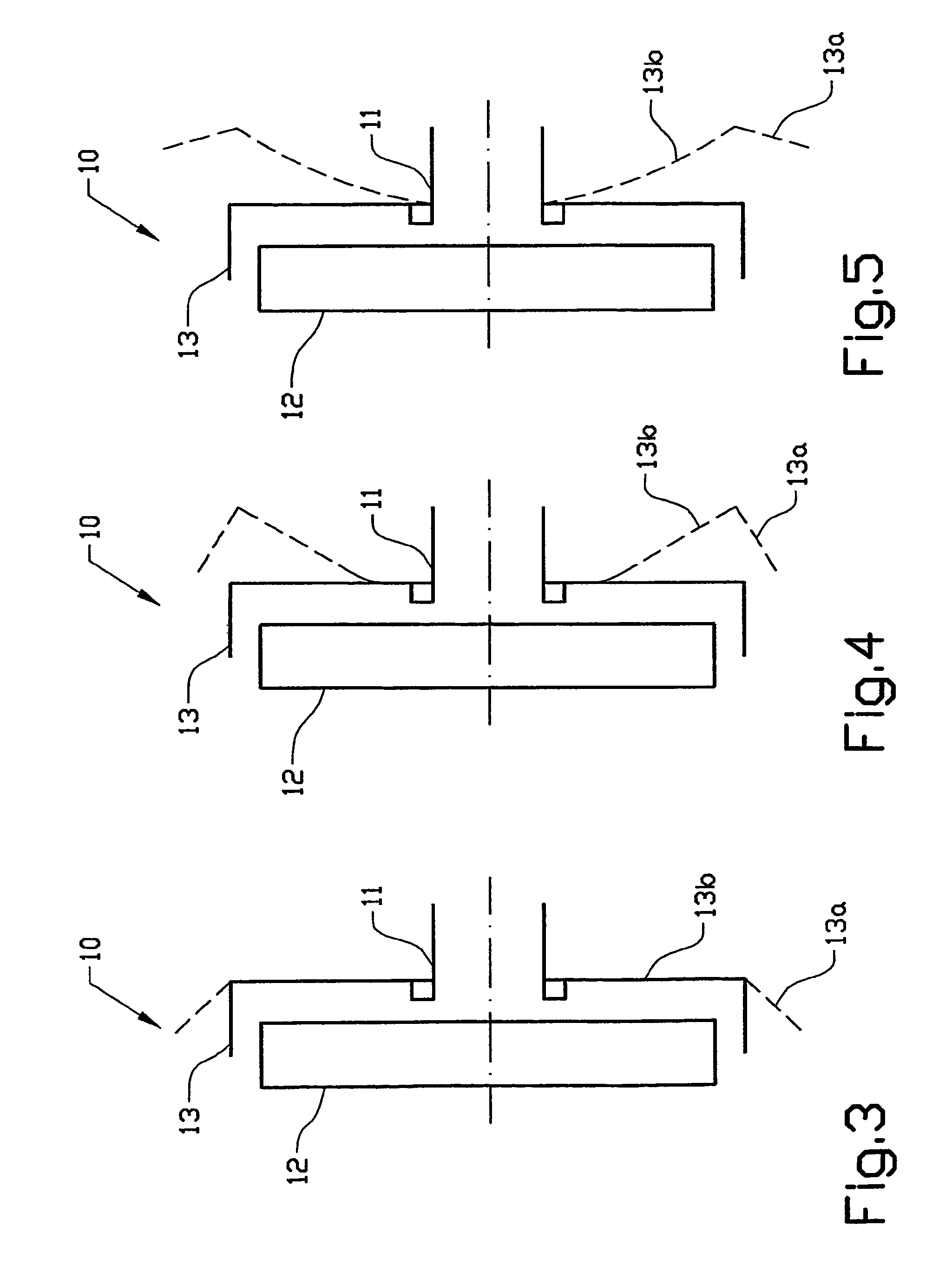
[0019]The protection device 10 shown in the figures is intended to be mounted on the wheel suspension 11, suitably at each of the wheels on a vehicle. The aim is to protect the brake disks 12 of the vehicle as well as possible from contact with degrading contamination, usually taking the form of dirt particles.

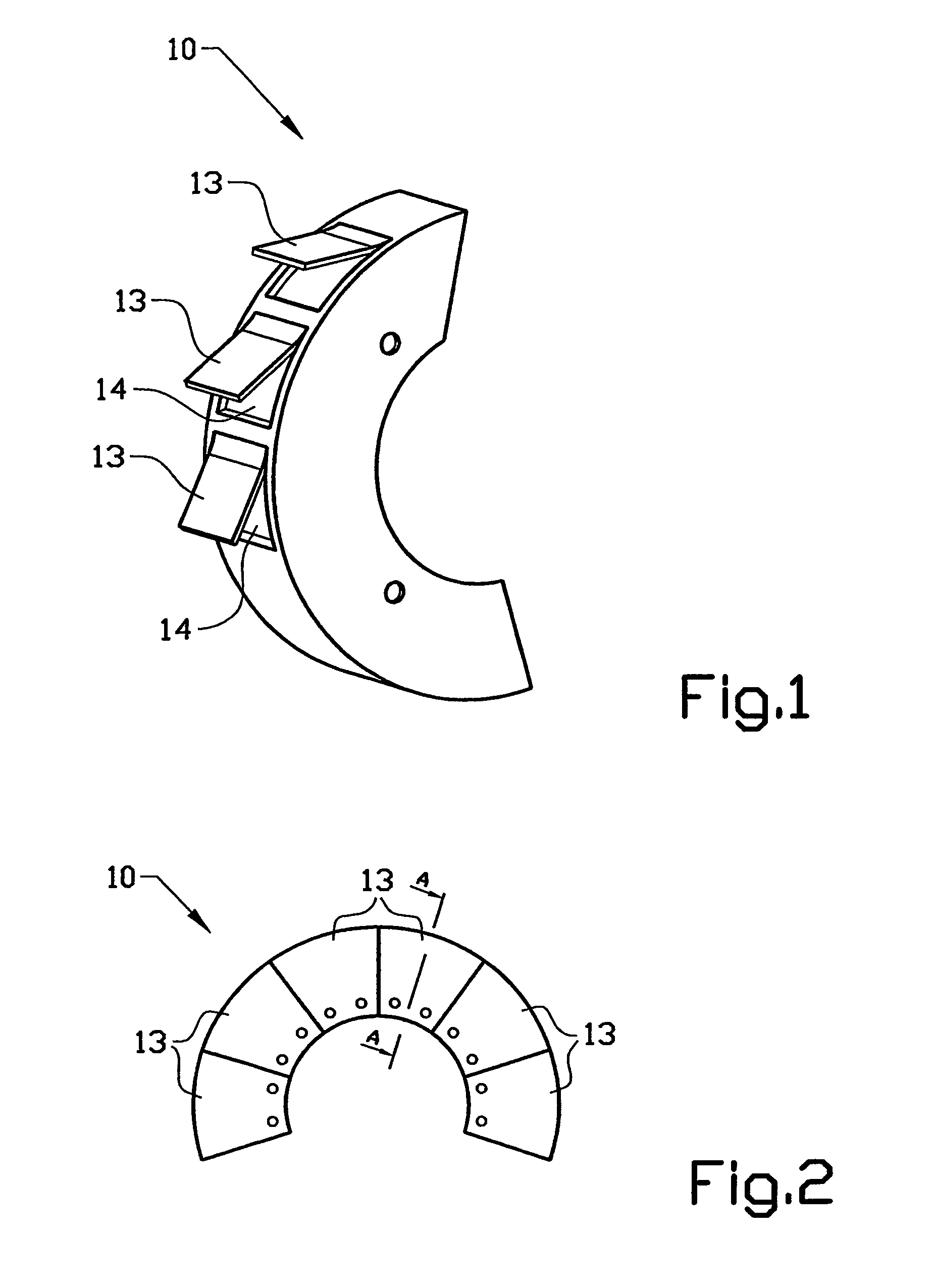
[0020]In the illustrative embodiment configured according to FIG. 1, the protection device forms a shield which is angled in an L-shaped manner around the edge of the brake disk 12. The shield is made from a material of which the shape is influenced by heat, preferably a bimetal sheet metal. A number of U-shaped punchings are made in the sheet metal, along the outer, peripheral portion of the shield. In this way, individual tongues 13 have been formed, which are arranged so as to be bent radially outward under the influence of heat. When the tongues 13 are bent outward, openings 14 are formed, which make it possible for cooling air to move past the shield and transport heat aw...


PUM


Abstract

A protection device (10) in a disk brake arrangement for protecting a brake disk (12) from dirt particles. The protection device at least partly surrounds the brake disk (12), and the protection device (10) includes at least one protection assembly (13) that is mounted on the wheel suspension (11) and consists at least partly of a material of which the shape is influenced by heat. The protection assembly has a first end position which prevents dirt particles and relative wind from striking the brake disk directly and a second end position which allows relative wind to strike the brake disk directly so as thus to obtain cooling of the brake disk. The first end position occurs when the temperature of the protection assembly lies below a first temperature and the second end position occurs when the temperature of the protection assembly exceeds a second temperature.

Description

CROSS-REFERENCE TO RELATED APPLICATIONS[0001]The present application is a continuation patent application of International Application No. PCT / SE03 / 00270 filed 19 Feb. 2003 which was published in English pursuant to Article 21(2) of the Patent Cooperation Treaty, and which claims priority to Swedish Application No. 0200493-5 filed 20 Feb. 2002. Said applications are expressly incorporated herein by reference in their entireties.TECHNICAL FIELD[0002]The present invention relates to a protection device for a disk brake, for protecting the brake disk from dirt particles, where the protection device is provided with at least one openable protection means for admission of heat-dissipating air for cooling the brake disk.BACKGROUND ART[0003]The functioning of disk brakes is affected negatively by contamination, which can lead to changes in friction, uneven wear and also corrosion on disks and linings. It is known to equip disk brakes with a protection plate so as to avoid contamination spa...

Claims


Application Information

Patent Timeline
Patent Type & Authority Patents(United States)
IPC IPC(8): F16D65/10F16D65/00F16D65/847
CPCB60B7/0086B60B19/10F16D65/0031F16D65/847F16D2065/783B60B2900/513
Inventor SABELSTROM, MATSBAGGE, LARS
Owner VOLVO LASTVAGNAR AB
Why Eureka
Try Eureka