[0043]According to the motor of the present invention, since an engaging force occurs as a result of interference between the convex section and the concave section when the direction in which a force that acts to split the stator core is displaced due to skewing in the laminated core segments, the laminated core segments can be connected to each other without welding or adhesive-bonding as conventionally practiced. As a result, the assembly operation of the stator core becomes easier, and a magnetically excellent connecting structure can be obtained.
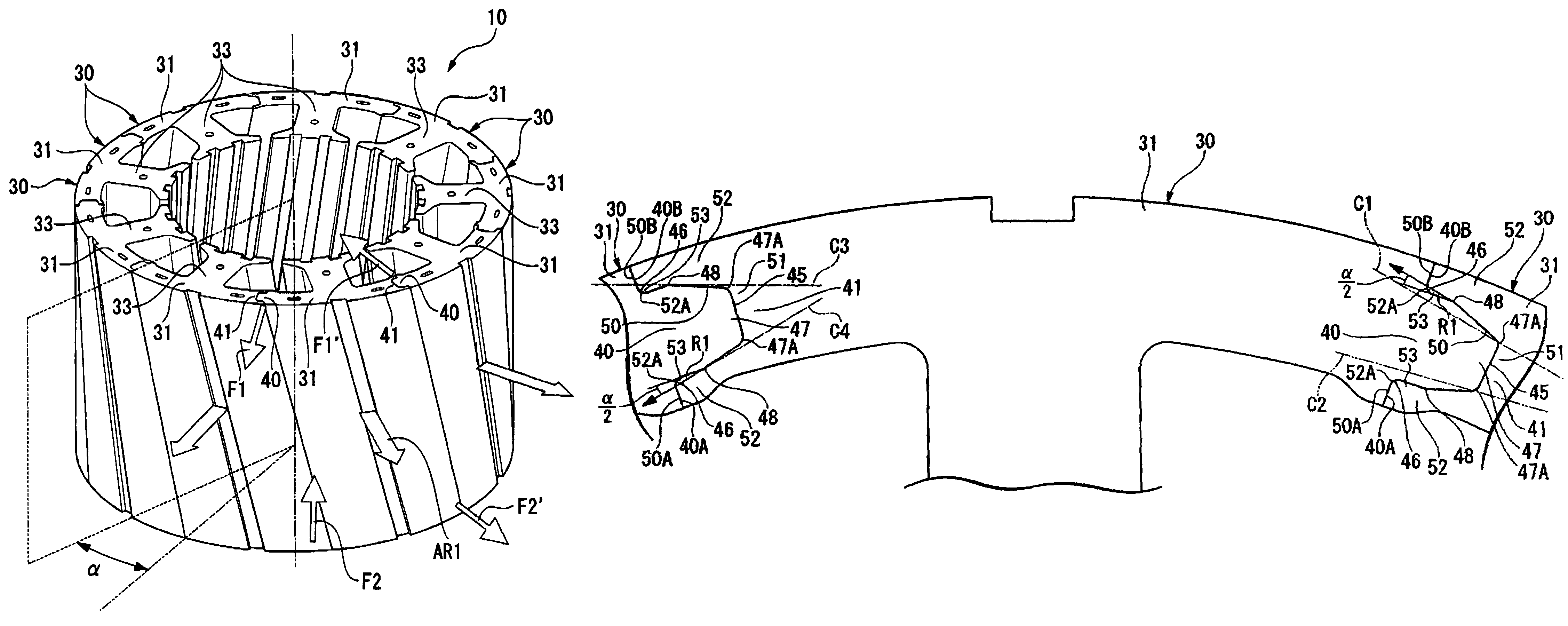
[0044]According to the stator of the rotary electric machine of the present invention, since the split core unit is formed by splitting, along the circumferential direction, the stator core formed by laminating a plurality of the ring-shaped plate members, and forming the stator by re-connecting the split core units, which have been split-formed from the same stator core, in a combination the same as that at the time of splitting, the adjacent split core units are connected to the split core units the same as those at the time prior to splitting, thereby enabling an improvement in the accuracy of the connection between the split core units. As a result, displacement or rattling that occurs in the connection section between the split core units can be suppressed, and steps or uneven gaps between the split core units can be prevented. Therefore, a variation in magnetic flux within the stator caused by steps in the split core units or uneven gaps can be suppressed, and a reduction in the characteristics of the rotary electric machine due to an impaired magnetic balance and a cogging torque can be reduced.
[0045]According to the stator of another rotary electric machine of the present invention, the split core unit is formed by splitting, along the circumferential direction, the stator core formed by laminating a plurality of the ring-shaped plate members in which the core pieces are connected along the circumferential direction, and the connection sections are cut-formed in the core piece by half-blanking the steel plate member, on which the plate member is formed, from one face side and then pressing it from the other face side. As a result, burrs in the connection face between the split core units can be prevented, and a variation in the thickness of the core piece can be suppressed, thereby enabling an improvement in the flatness of the core piece and the accuracy of the connection section. As a result, the lamination thickness of the respective split core units can be equalized and displacement or rattling in the connection section can be suppressed, enabling prevention of steps or uneven gaps between the split core units. Therefore, a variation in magnetic flux within the stator caused by steps in the split core units or uneven gaps can be suppressed, and a reduction in the characteristics of the rotary electric machine due to an impaired magnetic balance and a cogging torque can be reduced.
[0046]According to the manufacturing method of the stator of the rotary electric machine of the present invention, since the split core unit is formed by splitting, along the circumferential direction, the stator core formed by laminating a plurality of the ring-shaped plate members, and forming the stator by reconnecting the spilt core units, which have been split-formed from the same stator core, in a combination the same as that at the lime of splitting, the adjacent split core units are connected to the split core units the same as those at the time prior to splitting, thereby enabling an improvement in the accuracy of the connection between the split core units. As a result, displacement or rattling that occurs in the connection section between the split core units can be suppressed, and steps or uneven gaps between the split core units can be prevented. Therefore, a variation in magnetic flux within the stator caused by steps or uneven gaps in the split core units can be suppressed, and a reduction in the characteristics of the rotary electric machine due to an impaired magnetic balance and a cogging torque can be reduced.
[0047]According to the manufacturing method of the stator of another rotary electric machine of the present invention, the ring-shaped plate member in which the core pieces are connected in the circumferential direction is punch-formed from the steel plate member, and the steel plate member is half-blanked from one face side, and is then pressed from the other face side, thereby forming the connection section that connects the core pieces in between the adjacent core pieces. The stator core is formed by laminating a plurality of the plate members, and the stator core is split to form the split core unit. As a result, burrs in the connection face between the split core units can be prevented, and a variation in the thickness of the core piece can be suppressed, thereby enabling an improvement in the flatness of the core piece and the accuracy of the connection section. As a result, the lamination thickness of the respective split core units can be equalized and displacement or rattling in the connection section can be suppressed, enabling prevention of steps or uneven gaps between the split core units. Therefore, a variation in magnetic flux within the stator caused by steps or uneven gaps in the split core units can be suppressed, and a reduction in the characteristics of the rotary electric machine due to an impaired magnetic balance and a cogging torque can be reduced.
[0048]According to the rotary electric machine of the present invention, since the split core unit is formed by splitting, along the circumferential direction, the stator core formed by laminating a plurality of the ring-shaped plate members, and forming the stator by re-connecting the split core units, which have been split-formed from the same stator core, in a combination the same as that at the time of splitting, the adjacent split core units are connected to the split core units the same as those at the time prior to splitting, thereby enabling an improvement in the accuracy of the connection between the split core units. As a result, displacement or rattling that occurs in the connection section between the split core unit can be suppressed, and steps or uneven gaps between the split core units can be prevented. Therefore, a variation in magnetic flux within the stator caused by steps in the split core units or uneven gaps can be suppressed, and a reduction in the characteristics of the rotary electric machine due to an impaired magnetic balance and a cogging torque can be reduced.

