Feed-forward circuit for adjustable output voltage controller circuits

a controller circuit and output voltage technology, applied in the direction of electric variable regulation, process and machine control, instruments, etc., can solve the problems of long transient times, inability to completely remove the feed forward function from the end equipment, and many difficulties in traditional feed forward circuits, so as to improve the battery charging system performance, fast response, and quick stability

Active Publication Date: 2009-09-29
TEXAS INSTR INC
View PDF9 Cites 9 Cited by
  • Summary
  • Abstract
  • Description
  • Claims
  • Application Information

AI Technical Summary

Benefits of technology

[0011]In accordance with a preferred embodiment of the present invention, a battery charging system is provided for use with an adjustable output voltage AC-DC adapter containing a DC-DC power converter, in which the charging system includes a variable response control loop. An adapter output voltage based feed forward function is replaced with a variable bandwidth control loop function according to the present invention to provide a variable response and improve the battery charging system performance. An error signal is generated by control loops in the end equipment to indicate or command the desired adapter output. The error signal is provided to a feed forward circuit to modify the control loop response characteristics. For example, the control loop according to the present invention can be modified to have a faster response when a fast transient is detected, to help respond to the transient and quickly stabilize the system. The control loop can be returned to a slower response to provide better stability for variable loading situations, for example.
[0013]According to another aspect of a preferred embodiment of the present invention, a stability measure influences the modified response of the control loops to avoid stability problems that may be incurred with the faster response time. The stability measure can be operated as a timer or a pulse counter to obtain a time frame during which a stability indication is obtained. If a lack of stability is determined, the stability measure can be used to turn off the faster response time in the control loop to return the variable bandwidth control loop to a more stable mode of operation.
[0014]According to another aspect of a preferred embodiment of the present invention, the stability of the control loop is measured with respect to convergence to a desired point indicated by the width of a pulse. A timer or pulse counter may be used to determine an interval or number of resets that may occur in a short time frame that influence the operation of the control loop with respect to providing a faster response time. If the system operates in a range that converges to a desired steady state, the faster response aspect of the control loop may be disengaged to permit a more stable and slower response control circuit to operate. If the system is exposed to a large transient, the fast response time configuration may be applied repeatedly to obtain convergence, based on measurements taken over the interval or number of counts.

Problems solved by technology

However, with the more recent adapter output voltage control topology, with a power converter in the AC-DC adapter, a traditional feed forward circuit presents several difficulties, as the AC-DC adapter voltage dynamically changes under distinct system operating conditions as defined by the control loop.
Completely removing the feed forward function from the end equipment is not a viable option.
As a result, removing a feed forward function produces a very slow response to system load transients, potentially resulting in long transient times with a potential for excessive charge currents being applied to the battery pack.

Method used


Image

  • Feed-forward circuit for adjustable output voltage controller circuits
  • Feed-forward circuit for adjustable output voltage controller circuits
  • Feed-forward circuit for adjustable output voltage controller circuits

Examples


Embodiment Construction

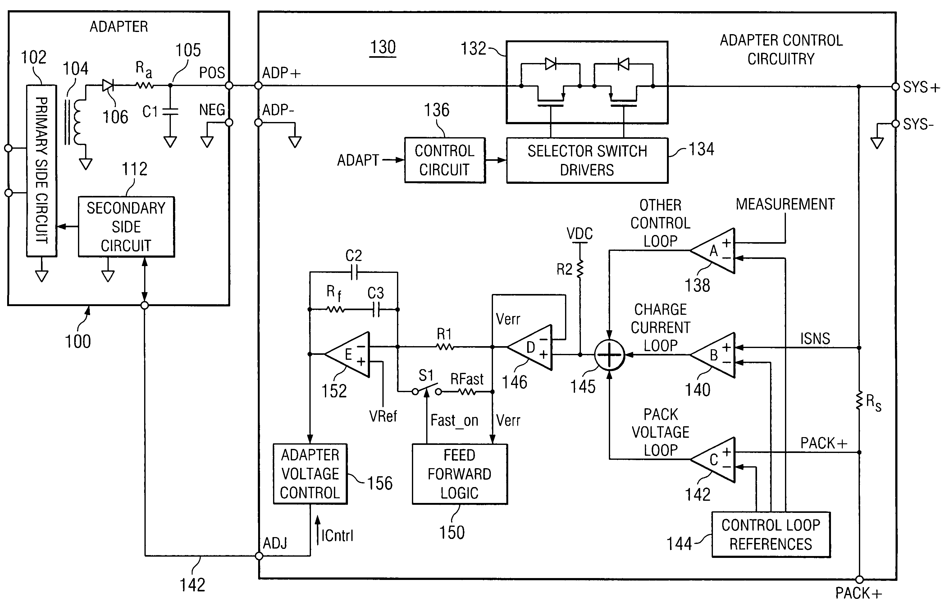
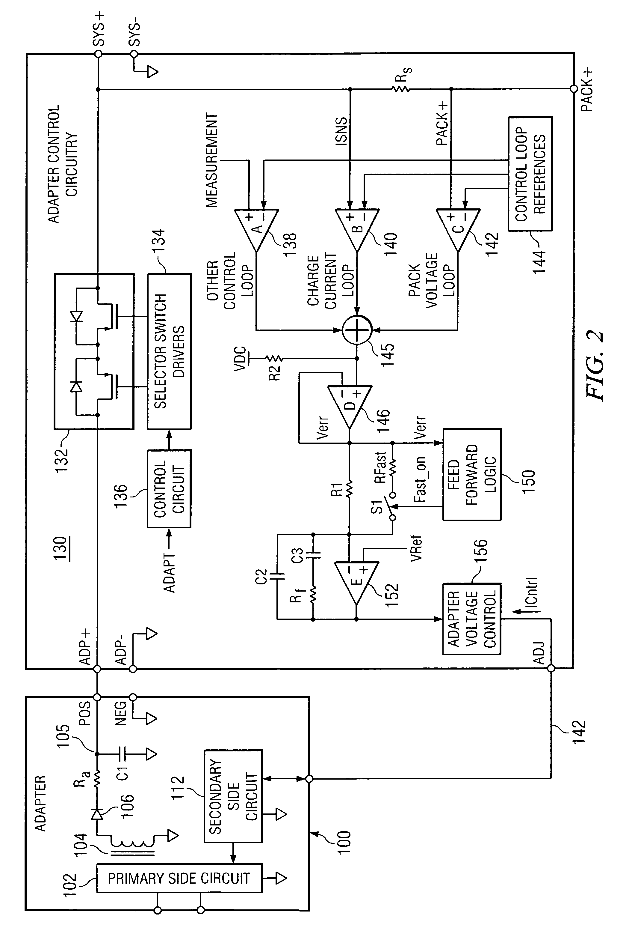
[0043]Referring now to FIG. 2, a battery charger control system in accordance with the present invention is illustrated generally as circuit 130. Circuit 130 is connected to an adapter circuit 100, which supplies regulated DC power to charger control circuit 130. DC regulation in circuit 100 is conventionally supplied through operation of a primary side circuit 102 that typically includes a switching bridge configuration that controls energy supplied to transformer 104. Conventionally, a reading of output voltage 105 from adapter circuit 100 is used to provide adapter circuit 100 with a feedback signal to control voltage output to charge control circuit 130.

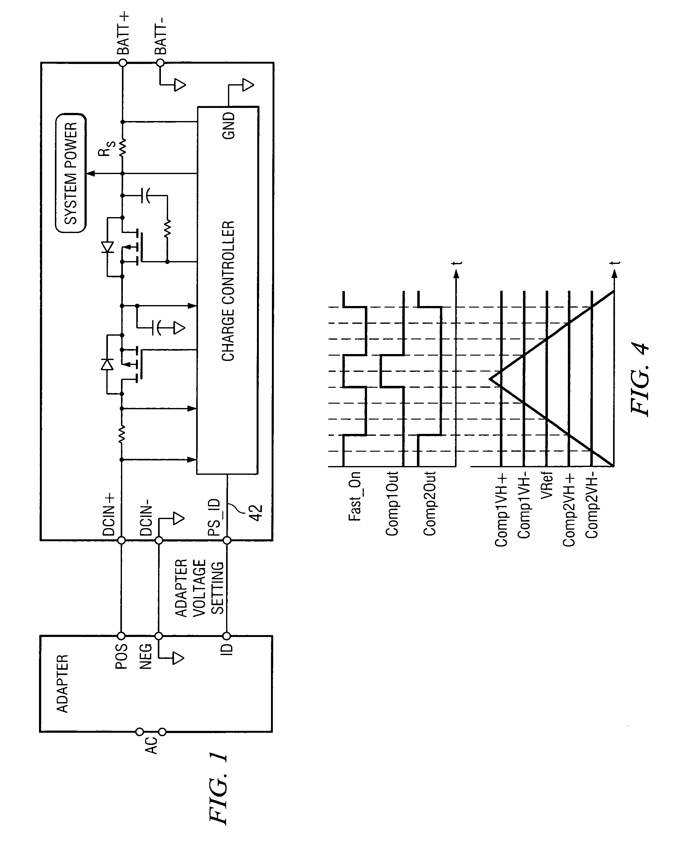
[0044]In variable output power adapters an error signal is typically supplied from the controller to the adapter, such as error signal 42 indicated in FIG. 1. In accordance with the present invention, the feed forward control is provided in charge control circuitry 130. FIG. 2 illustrates the generation of error signal 142 provid...


PUM


Abstract

A feedback loop in a variable power supply has an adjustable response speed based on operating conditions of the power supply. The response speed can be increased upon encountering a transient to improve response performance to the transient. A response speed control for the control loop modifies or bypasses a major low frequency pole in a compensation network in the control loop to increase response speed. The control limits fast response duration or impact with respect to the low frequency pole to avoid instability issues. The control may include counters or timers to selectively disable or enable the fast response function. The control can operate based on an error feedback signal and a reference to determine when a fast response should be applied. The resulting power supply system provides robust, well-regulated power, with fast responses to system transients.

Description

BACKGROUND OF THE INVENTION[0001]1. Field of the Invention[0002]The present invention relates generally to a feed-forward control for power supplies used in battery chargers, and relates more particularly to a dynamic feed back control adaptive to transient events.[0003]2. Description of the Related Art[0004]Battery chargers for various applications including portable personal computers have been developed over the course of a number of years to improve performance characteristics while reducing size and complexity. Battery chargers are typically connected to an input power supply also used in powering an application such as a portable PC. In conventional topologies in portable end equipment, such as a portable PC, the battery charger is located in the end equipment and draws its power from an AC / DC power converter. The AC / DC converter supplies a consistent, fixed voltage to the battery charger, in addition to supplying power to the application. In this traditional topology, a power...

Claims


Application Information

Patent Timeline
Patent Type & Authority Patents(United States)
IPC IPC(8): G05F1/40
CPCH02J7/04H02J7/007
Inventor VIEIRA FORMENTI, JOSE ANTONIO
Owner TEXAS INSTR INC
Why Eureka
Try Eureka