Flow cell consisting of layer and connection means

a flow cell and connection means technology, applied in the field of flow cells with layered arrangements, can solve problems such as the risk of chemical and biological contamination of the environment, and achieve the effect of less expense and reliable production

Active Publication Date: 2009-09-29
THINXXS MICROTECHNOLOGY AG
View PDF28 Cites 27 Cited by
  • Summary
  • Abstract
  • Description
  • Claims
  • Application Information

AI Technical Summary

Benefits of technology

[0009]The objective of the present invention is to create a new flow cell of the aforementioned type, which can be reliably produced and operated with less expense than previously known flow cells of this type and in which separately prefabricated units can be integrated, such as micropumps, microvalves, fluid reservoirs, and the like.

Problems solved by technology

After the flow cell has been removed from the external clamping device, the connection between the plates is broken, and this results in the risk of chemical and biological contamination of the environment.

Method used


Image

  • Flow cell consisting of layer and connection means
  • Flow cell consisting of layer and connection means
  • Flow cell consisting of layer and connection means

Examples


Embodiment Construction

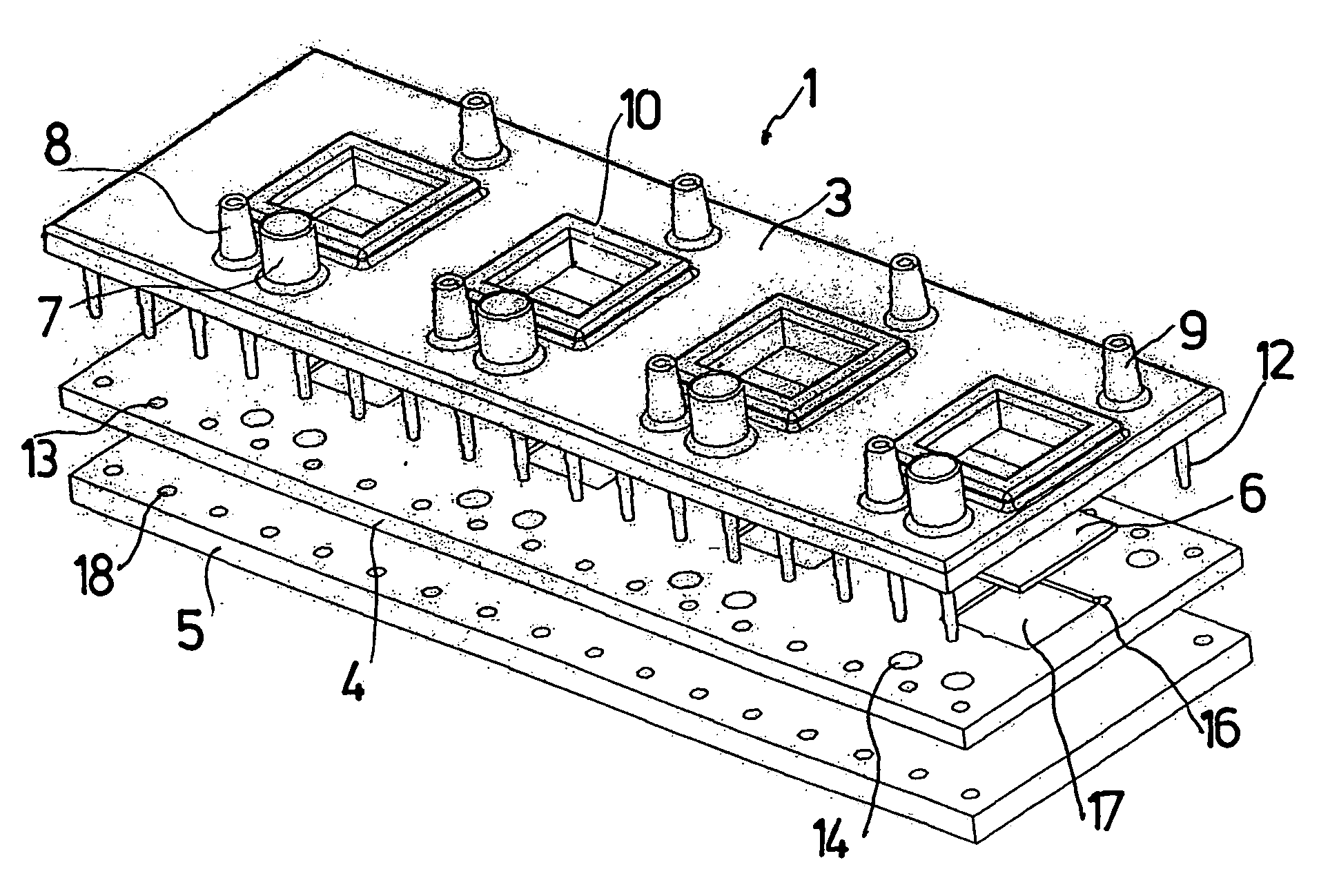
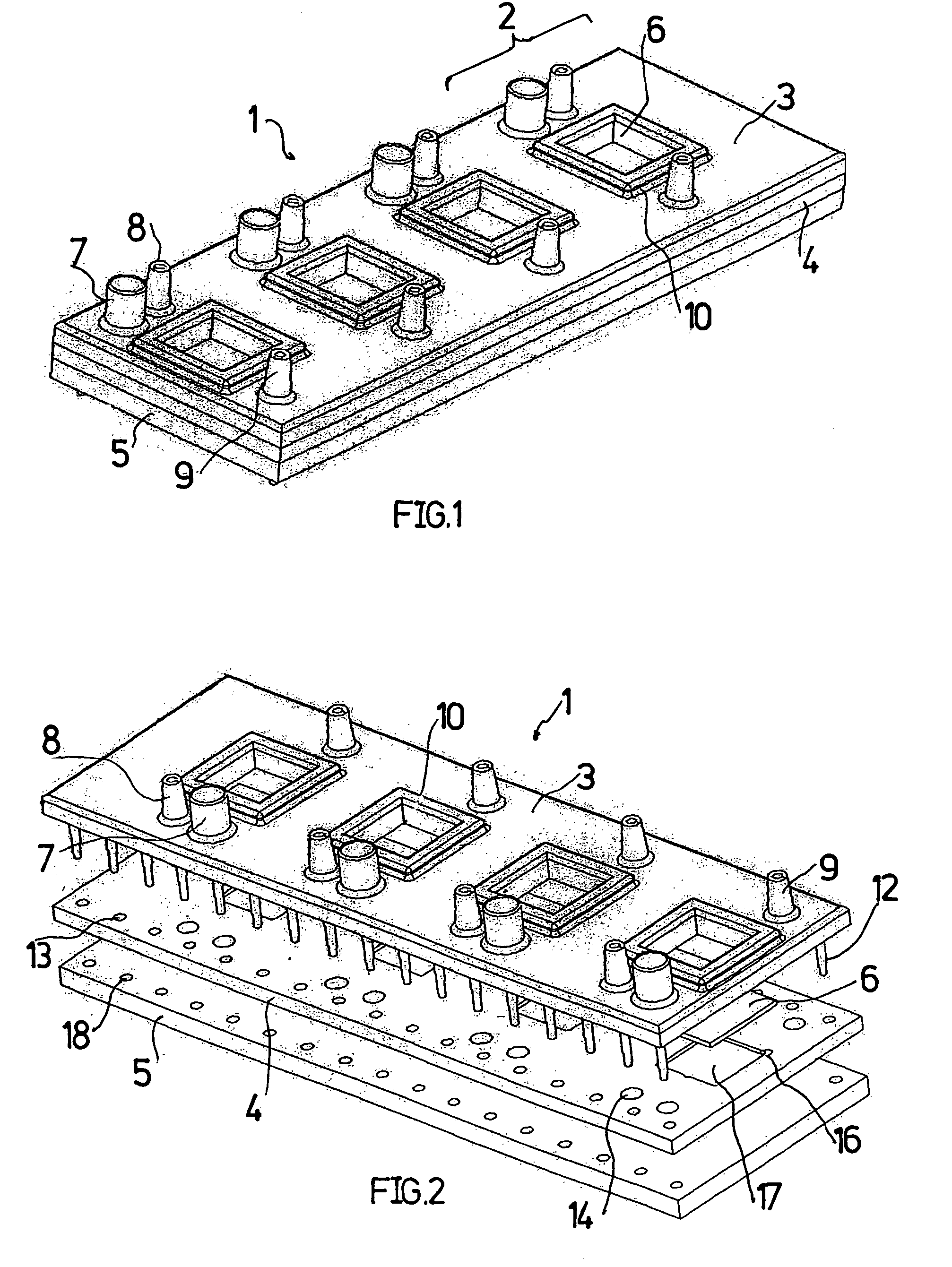
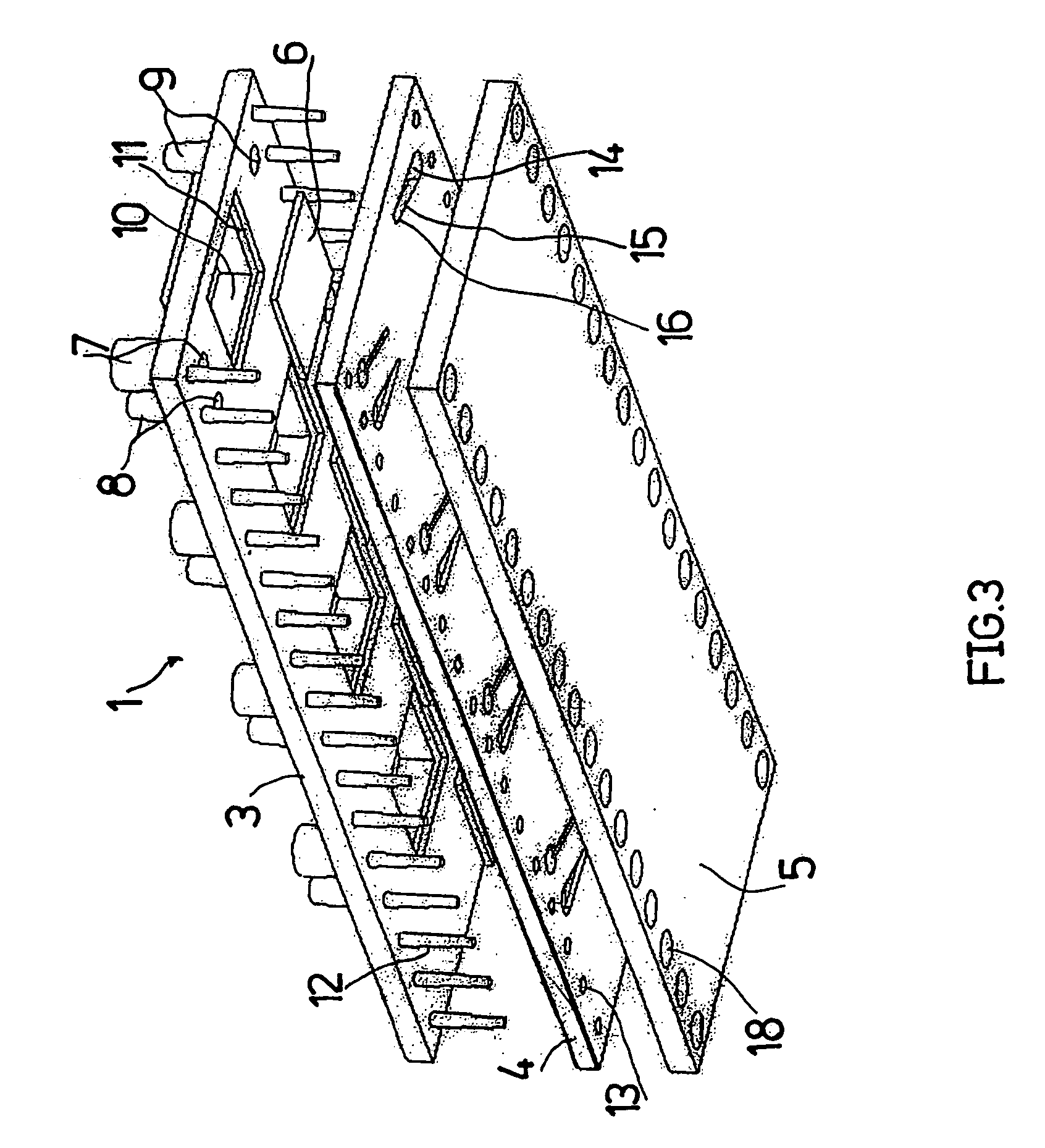
[0043]The flow cell illustrated in FIGS. 1 to 3 has a cover plate 3, an intermediate plate 4, and a base plate 5. In the illustrated embodiment, the flow cell contains four identical functional units 2. The plates 3 to 5 are produced by replication methods, preferably micro injection molding. The outside dimensions of the plates are 5 to 200 mm, and the thickness of the plates is 0.5 to 10 mm.

[0044]Each functional unit 2 contains connections 7, 8, 9 which are formed as integral parts of the cover plate 3 on the upper surface of the cover plate, one connection in the form of a reservoir or well 7, and flexible tube connections 8 and 9. In addition, each functional unit 2 contains a microcomponent 6, which can be inserted from below in a cavity 10 that is formed in the cover plate 3 and passes completely through it.

[0045]As FIG. 3 shows, the rectangular cavity 10 has a shoulder 11 that serves as a seat for the microcomponent 6. The lateral dimensions of the cavity 10 in the area of th...


PUM

PropertyMeasurementUnit
thicknessaaaaaaaaaa
thicknessaaaaaaaaaa
thicknessaaaaaaaaaa

Abstract

The invention relates to a flow cell comprising a layered arrangement of three plates (3-5) in which an intermediate plate (4) consisting of a flexible material is inserted between plates (3, 5) consisting of a more solid material, and at least one of the plates comprises at least one recess (15, 17) for receiving fluid, that is bordered by another plate (3, 5) of the layered arrangement. Such recesses are especially microchannels and reaction chambers. According to the invention, the plates are interconnected by means arranged parallel to the plate plane at a distance to the recess, compressing the intermediate plate.

Description

BACKGROUND OF THE INVENTION[0001]1. Field of the Invention[0002]The invention concerns a flow cell with a layered arrangement of three plates, in which an intermediate plate made of a flexible material is held between plates made of a more rigid material, and at least one of the plates has at least one recess for holding fluid, which recess is bounded by another plate of the layered arrangement.[0003]2. Description of the Related Art[0004]Miniaturized flow cells of this type are finding increasing use in analysis and sensor technology in the field of chemistry, especially biochemistry, and in medicine, especially diagnostics. The aforementioned recess can form, e.g., a microchannel, a reaction chamber with a fluid connection with the microchannel, and / or a chamber for holding a sensor, such that the dimensions of these recesses in at least one direction in space can vary between a few tens of micrometers to 100 micrometers. Depending on their construction and outfitting, flow cells ...

Claims


Application Information

Patent Timeline
Patent Type & Authority Patents(United States)
IPC IPC(8): G01N1/10B01L3/00B29C65/58B29C65/60B29C65/78
CPCB01L3/5025B29C66/543B29C65/58B29C65/606B29C65/607B29C65/7802B29C65/7811B01L3/502707B01L3/50273B01L3/502738B01L2200/025B01L2200/0689B01L2200/10B01L2300/0645B01L2300/0681B01L2300/0822B01L2300/0874B01L2300/0877B01L2300/0887B01L2300/1827B01L2400/0406B01L2400/0415B01L2400/0481B01L2400/0487B29L2031/756B29C65/7814B29C66/71B29K2021/003B29K2023/12B29K2023/38B29K2025/06B29K2033/12B29K2069/00B29K2071/00B29K2075/00B29K2083/00
Inventor WEBER, LUTZ
Owner THINXXS MICROTECHNOLOGY AG
Why Eureka
Try Eureka