Multi-leaf collimator

a collimator and multi-leaf technology, applied in the field of multi-leaf collimators, can solve the problems of increased likelihood of recurrence, increased side effects, and longer recovery time after treatment, so as to reduce the weight of the material, save the weight, and reduce the weight

Active Publication Date: 2009-09-29
ELEKTA AB
View PDF4 Cites 37 Cited by
  • Summary
  • Abstract
  • Description
  • Claims
  • Application Information

AI Technical Summary

Benefits of technology

[0014]That or other leaves can also have a rack formed on an edge of the actuator section distal the respective leaf. Thus, some leaves can be driven via pinions mounted on shafts passing over the array, and other leaves can be driven via pinions mounted on shafts passing within the gaps between leaves and actuators. This means that twice the number of drive shafts can be fitted into the same length of array, thus either shortening the array or permitting more leaves and hence greater resolution.
[0016]A separate drive unit is advantageous in manufacturing as it allows the drive unit to be produced, built and tested as a separate assembly in a specialist environment. Service replacement of the entire gearbox in the event of a fault will also be swifter, with minimal re-setting. It is likely that the replacement of such a gearbox will take considerably less time than the replacement of the sum of individual component parts that constitute existing drive technologies.
[0018]The invention also offers a major advantage in the leaf length is no longer dictated by the length of the rack. The leaf can be made smaller, saving material and reducing its weight. That reduction in weight will make movement of the leaf easier, improving both accuracy and reliability.

Problems solved by technology

If areas are left untreated then the likelihood of recurrence is increased, whereas if non-treatment regions are irradiated then damage will be caused to healthy tissue resulting in greater side effects and longer recovery times after treatment.
A significant problem in doing so is the need to drive the leaves, i.e. provide a means of physically moving them to the required degree of accuracy, and the impact of this on the length of a leafbank, the length of a leaf, and its the complexity and serviceability.
This in turn increases the size of the treatment head and can restrict the patient treatment access.
If the leaves are driven from one end, then the motors are outboard and undesirably add length to the assembly.
Likewise, reductions in the leaf width mean that it becomes increasingly difficult to embed a leadscrew.
The existing rack & pinion methods also become increasingly difficult with a larger number of leaves, and usually result in extending the leaf length in order to accommodate the necessary number of motor drives.

Method used


Image

  • Multi-leaf collimator
  • Multi-leaf collimator
  • Multi-leaf collimator

Examples


Embodiment Construction

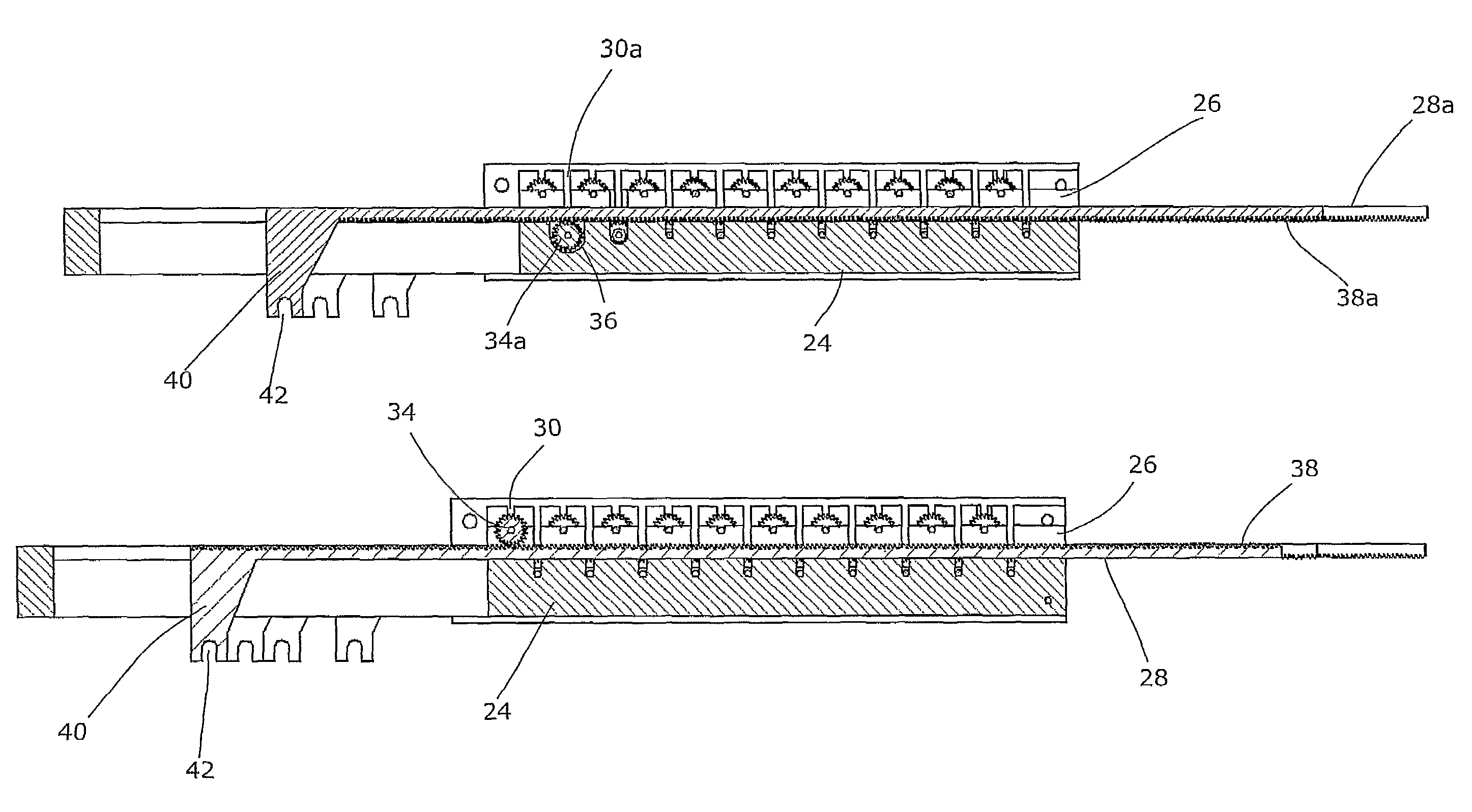
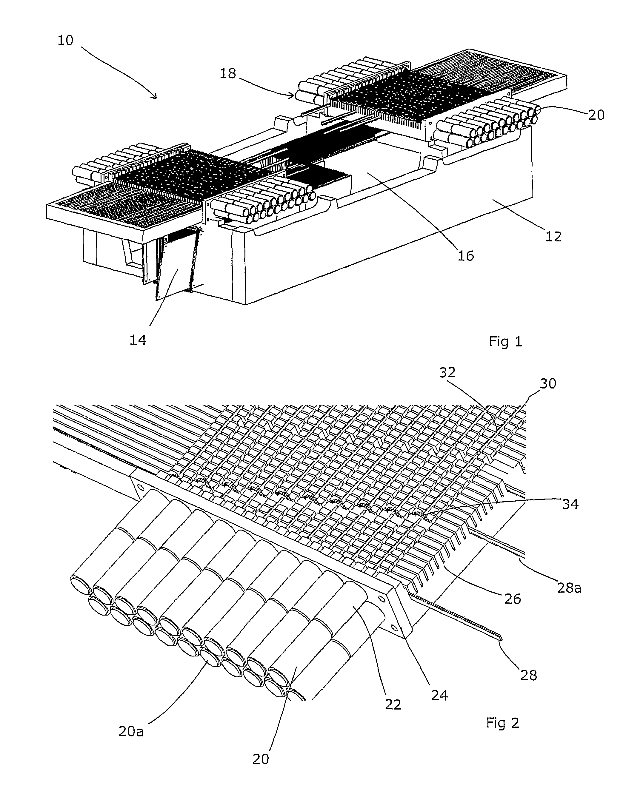
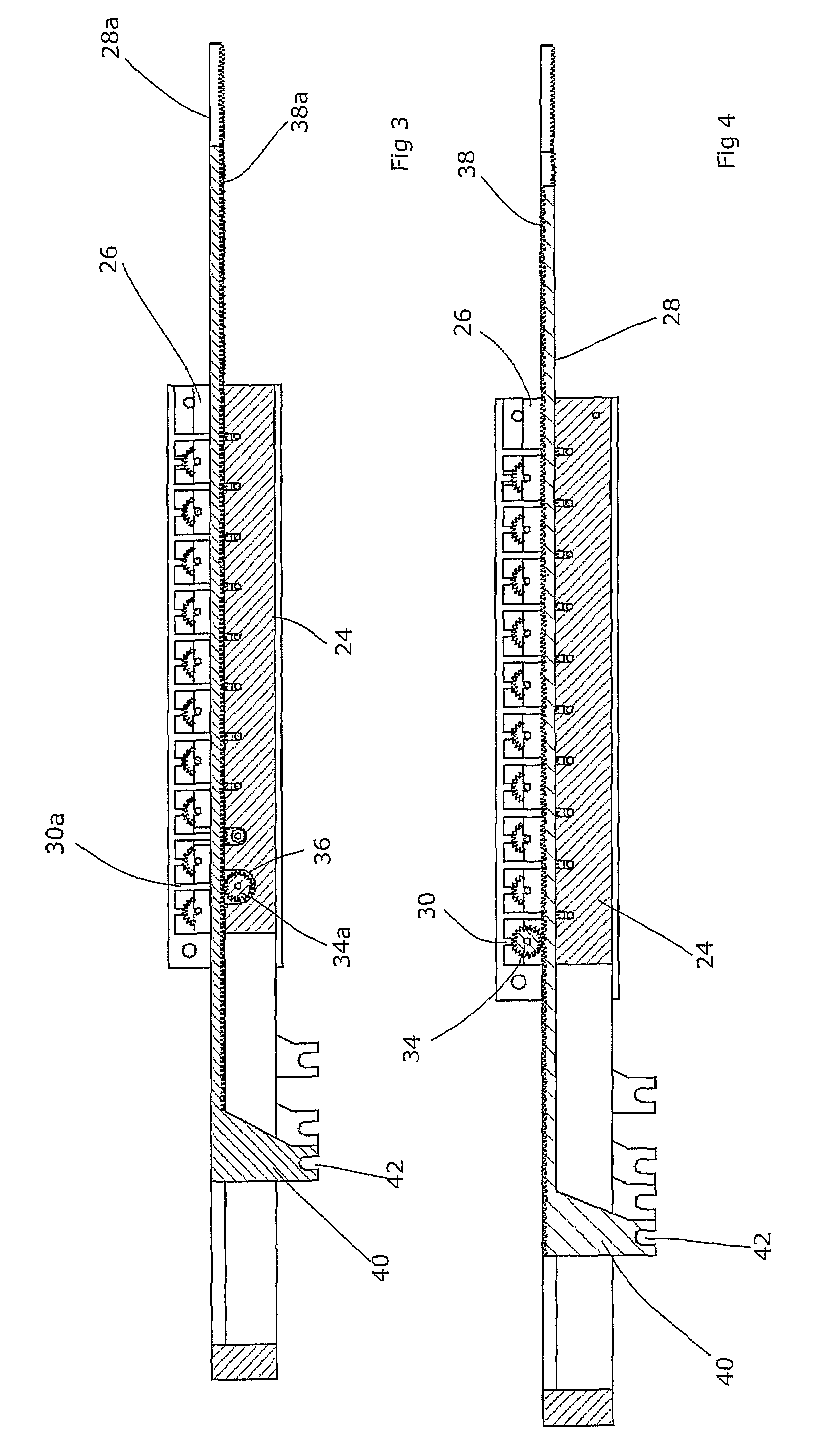
[0027]FIG. 1 shows a multi-leaf collimator 10. A housing 12 contains two opposing arrays of elongate leaves 14, a selection of which are shown in FIG. 1. These leaves 14 are each moveable longitudinally within the array so that they can each project by a greater or lesser distance into the open space 16 disposed generally in the middle of the housing 12. In use, a beam of radiation is directed through that open space 16 and its extent is collimated by the leaves 14. The leaves are relatively thin so as to allow a high resolution to be obtained, but they are relatively deep in the direction of the beam in order to render them fully opaque at X-ray energies. The leaves 14 are relatively elongate so as to allow them to adopt a wide range of positions.

[0028]For each array of leaves 14, there is a drive unit 18. This has arrays of motors 20 on either side, each of which is associated with an individual leaf. A suitable micro-processor will typically be provided (not shown) which will pro...


PUM


Abstract

A multi-leaf collimator comprises an elongate leaf moveable in a longitudinal direction, and having an associated toothed rack driven by a pinion, wherein the rack is carried on an elongate actuator section, having a transversely extending link section, the leaf being connected to the link section and thereby being spaced from the actuator section.

Description

FIELD OF THE INVENTION[0001]The present invention relates to a multi-leaf collimator.BACKGROUND ART[0002]Multi-leaf collimators (MLC) are used (principally) in the field of radiotherapy. A beam of radiation is directed toward a patient and must be collimated to fit the shape of the area to be treated. It is important to ensure that the dose in the areas outside that shape is as low as possible, but also that the whole area is treated. If areas are left untreated then the likelihood of recurrence is increased, whereas if non-treatment regions are irradiated then damage will be caused to healthy tissue resulting in greater side effects and longer recovery times after treatment.[0003]As the treatment area is rarely rectilinear, multi-leaf collimators are employed. These comprise an array of finger-shaped leaves of a radiation-absorbing material, each disposed in a parallel relationship and each able to move longitudinally relative to the others. By moving each leaf to a selected positi...

Claims


Application Information

Patent Timeline
Patent Type & Authority Patents(United States)
IPC IPC(8): G21K1/04A61N5/10
CPCA61N5/1042G21K1/046G21K1/04A61N5/10
Inventor PERKINS, CLIFFORD WILLIAM
Owner ELEKTA AB
Why Eureka
Try Eureka