Microwave drying of ceramic structures

a technology of ceramic structures and microwaves, applied in the direction of electric/magnetic/electromagnetic heating, lighting and heating apparatus, etc., can solve the problems of reduced structural strength, inability of microwave radiation to properly penetrate into and effect uniform heating within the interior portions, and inability to reduce heat-induced structural degradation. , to achieve the effect of uniform drying and reducing heat-induced structural degradation

Active Publication Date: 2009-10-06
CORNING INC
View PDF21 Cites 64 Cited by
  • Summary
  • Abstract
  • Description
  • Claims
  • Application Information

AI Technical Summary

Benefits of technology

[0012]The present invention relates to a method for drying a thin-walled ceramic structure such as a honeycomb comprising providing microwave radiation from a microwave generating source, providing a ceramic honeycomb structure having a middle portion and at least one end, and exposing the ceramic honeycomb structure to the microwave radiation. The method further includes shielding at least one end of the ceramic honeycomb structure from directly receiving the microwave radiation, such that the radiation absorbed by the middle portion is equal to or greater than the radiation absorbed by the at least one end. Uniform drying of the ceramic substrate with reduced heat-induced structural degradation is thereby promoted. The radiation absorbed by the middle portion is preferably within the range of from about 0% to about 60% greater than the radiation absorbed by the at least one end, and more preferably within the range of from about 10% to about 40% greater than the radiation absorbed by the at least one end.
[0013]The present method is highly accurate and repeatable, may be completed in a relatively short cycle time, is relatively easy to perform, and results in a filter with relatively greater structural integrity with reduced deformation and degradation. The method further reduces the relative cracking and stress fractures within the desired structure produced during the drying process, reduces manufacturing costs associated with cycle times, is efficient to use, and is particularly well-adapted for the proposed use.

Problems solved by technology

Some previous methods used for drying ceramic honeycomb structures have led to decreased structural strength due to heat-induced structural degradation.
Structural strength requirements are particularly demanding for ceramic catalyst substrates and filters to be used in the mechanically harsh environment of motor vehicle exhaust emissions control systems.
Also problematic from a drying standpoint are honeycombs directly incorporating materials such as transition metal oxide catalysts, where the catalysts include constituents that are semiconductive or very lossy at the desired microwave drying frequency.
These drying difficulties are attributed to the inability of microwave radiation to properly penetrate into and effect uniform heating within the interior portions of such materials, due to reduced microwave permeability occasioned by the presence of graphite or other lossy materials within the ceramic batch mixtures.
The consequence is that the drying of such honeycombs using microwave radiation can lead to unacceptable localized heating, which in turn leads to unstable processing, poor select rates, and lower quality ware.
For example, the drying of an aluminum titanate substrate with a 30% graphite additive has produced unwanted edge heating that results in cracks and / or contour problems in the associated filter.
This solution is obviously inefficient and creates a significant amount of waste.
However, each of these alternatives requires accepting unwanted compromises, such as lower quality end products and / or increases in manufacturing costs.

Method used


Image

  • Microwave drying of ceramic structures
  • Microwave drying of ceramic structures
  • Microwave drying of ceramic structures

Examples


Embodiment Construction

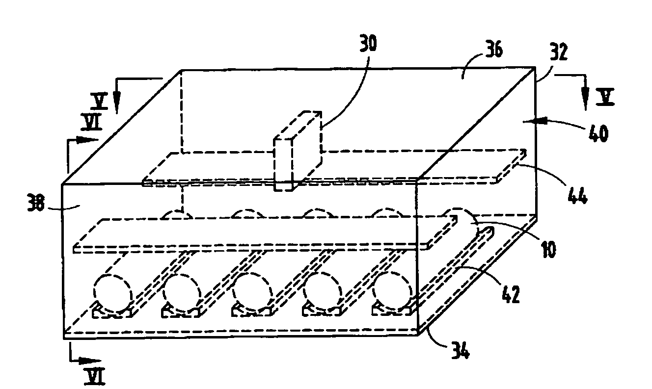
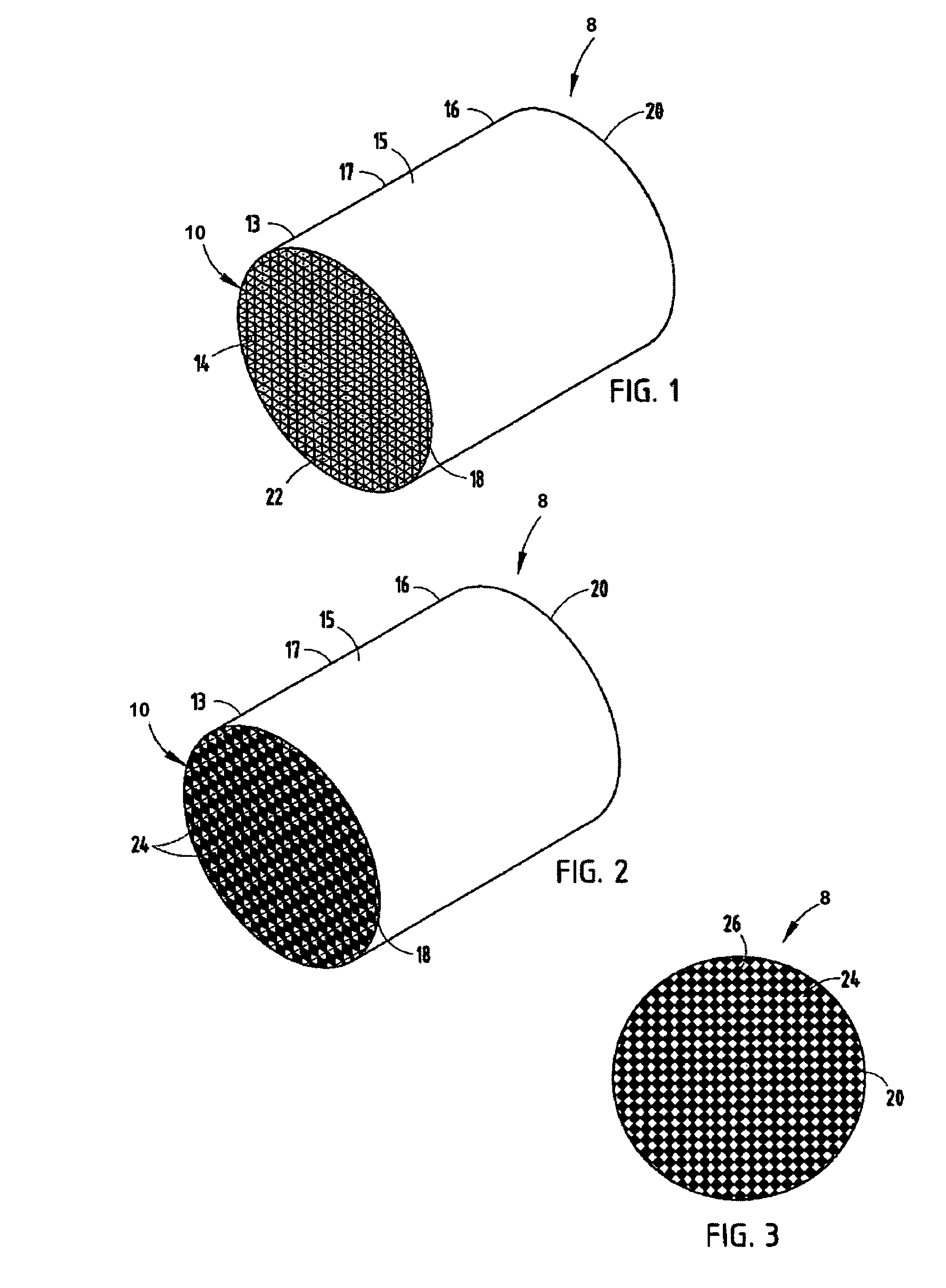
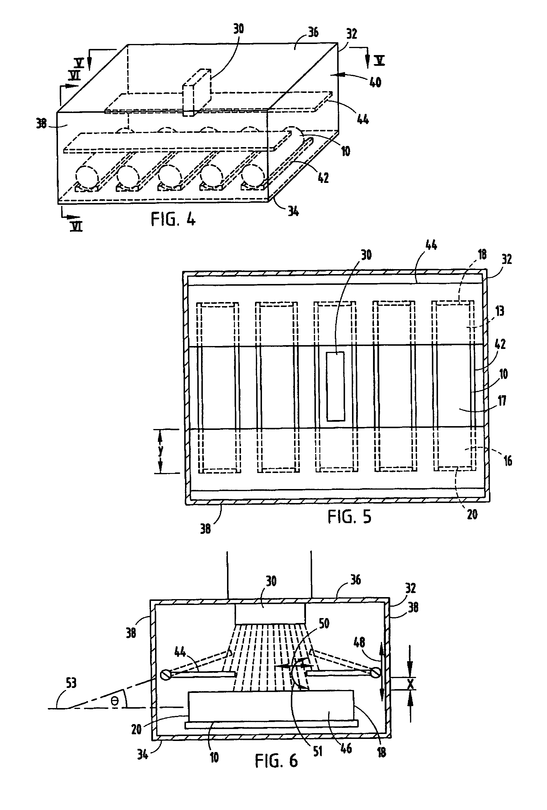
[0031]Several methods and procedures are known in the art for forming green ceramic honeycomb structures featuring a plurality of hollow passages or channels extending therethrough. The present inventive process is directed to drying such structures regardless of the specific method used to form the honeycomb shape. The present inventive method for drying ceramic honeycomb structures 10 includes providing microwave radiation from a microwave generating source 30 (FIGS. 4-6) located within a microwave housing 32, exposing the ceramic honeycomb structure 10 to the microwave radiation, and shielding at least one of the ends 13, 16 from directly receiving the microwave radiation, such that the radiation absorbed by the middle portion 17 of the ceramic structure 10 is equal to or greater than the radiation absorbed by the at least one end 13, 16, as described herein. It is noted that the present inventive process may be used to process either plugged or non-plugged ceramic structures.

[00...


PUM

PropertyMeasurementUnit
angleaaaaaaaaaa
angleaaaaaaaaaa
angleaaaaaaaaaa

Abstract

A method for drying a ceramic article comprises providing microwave radiation from a microwave generating source, providing a ceramic honeycomb structure having a middle portion and at least one end, and exposing the ceramic honeycomb structure to the microwave radiation while shielding the at least one end from directly receiving the microwave radiation, such that the radiation absorbed by the middle portion is equal to or greater than the radiation absorbed by the at least one end, and the proper drying of the entire honeycomb structure without heat-induced structural degradation is thus ensured.

Description

BACKGROUND OF THE INVENTION[0001]The present invention relates to a method for drying ceramic articles via a microwave dryer, and in particular to methods for drying ceramic honeycomb structures via a microwave dryer that promotes uniform drying of the honeycomb structures, thereby relieving or eliminating heat-induced structural degradation of the structures.[0002]Ceramic honeycomb structures having transverse cross-sectional cellular densities of approximately one-tenth to 100 or more cells or channels per square centimeter of honeycomb cross-section have several uses, including use as particulate filter bodies, catalyst substrates, and stationary heat exchangers. Filter applications generally require that selected cells of the structure be sealed or plugged at one or both of the respective ends thereof in a manner such that wall-flow filtration, i.e., the filtering of fluids traversing the structure by directing at least some of those fluids through porous channel walls thereof, ...

Claims


Application Information

Patent Timeline
Patent Type & Authority Patents(United States)
IPC IPC(8): F26B3/28H05B6/64
CPCB28B11/241B28B11/243F26B3/347B28B11/248F26B2210/02
Inventor ADRIAN, PAUL ANDREASFELDMAN, JAMES ANTHONYGEORGE, JACOBVILENO, ELIZABETH MARIE
Owner CORNING INC
Why Eureka
Try Eureka