Structural wall coupling system

a technology of structural walls and couplings, applied in the direction of building repairs, parkings, shock proofing, etc., can solve the problems of reducing the cost of reinforcing, reducing the amount of reinforcing in shear walls, and creating potentially harmful bending moments and flexural demands

Inactive Publication Date: 2009-10-06
HIGHRISE CONCRETE SYST
View PDF18 Cites 0 Cited by
  • Summary
  • Abstract
  • Description
  • Claims
  • Application Information

AI Technical Summary

Benefits of technology

[0017]Thus, the building, as coupled by the rigid member, is converted from a cantilevered beam to a vertical truss, thereby distributing the shear and flexural forces due to lateral loads in such a way so as to resist seismic and other such actions without increasing the thickness of the shear walls or the amount of reinforcing used in the shear walls.

Problems solved by technology

Because buildings act like vertical cantilever beams, the shear forces exerted on the buildings create potentially harmful bending moments and flexural demands.
However, it is very desirable to maintain thin shear walls and limit the amount of reinforcing in shear walls.
Thin shear walls and reduced reinforcing decreases costs and increases the speed of construction.
However, even with tunnel forming, bottom-heavy flexural forces pose a problem.
With typical shear wall structures, lateral loads from any direction cause undesired shear forces and flexural demands.
Thus, even though tunnel forming partially reduces the problem with shear forces and flexural demands, it does not completely eliminate the problem.
Consequently, conventional shear wall structures, tunnel form structures, as well as other building structures are susceptible to shear forces in any direction, thereby necessitating increased flexural resistance in such buildings without the use of thicker structural or shear walls, or increased reinforcing.

Method used


Image

  • Structural wall coupling system
  • Structural wall coupling system
  • Structural wall coupling system

Examples


Embodiment Construction

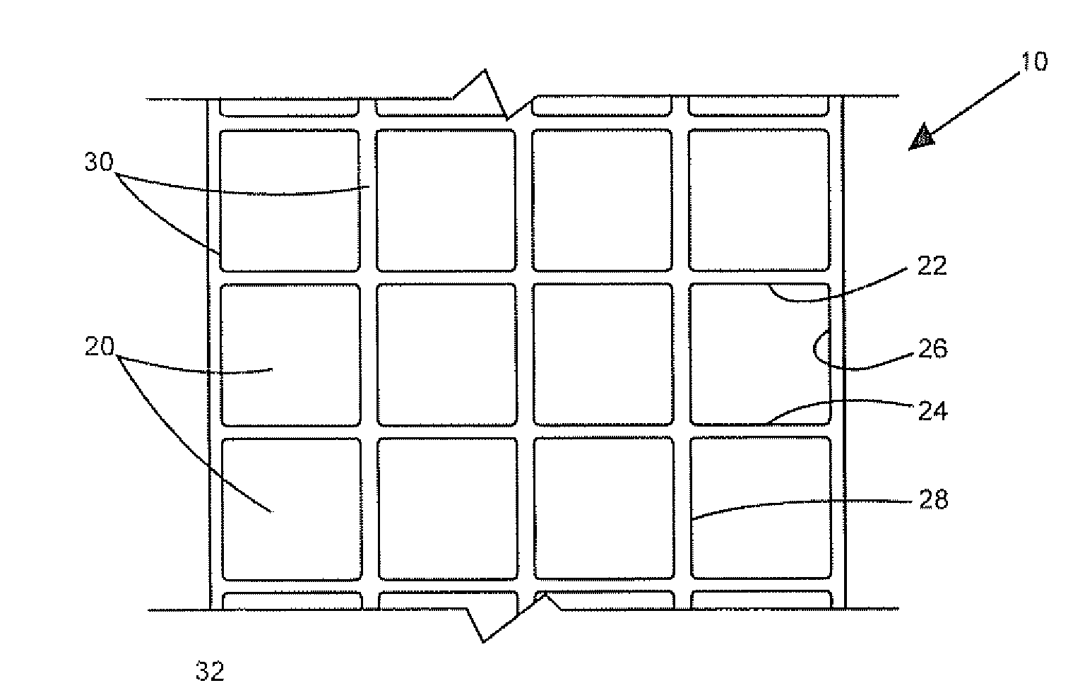
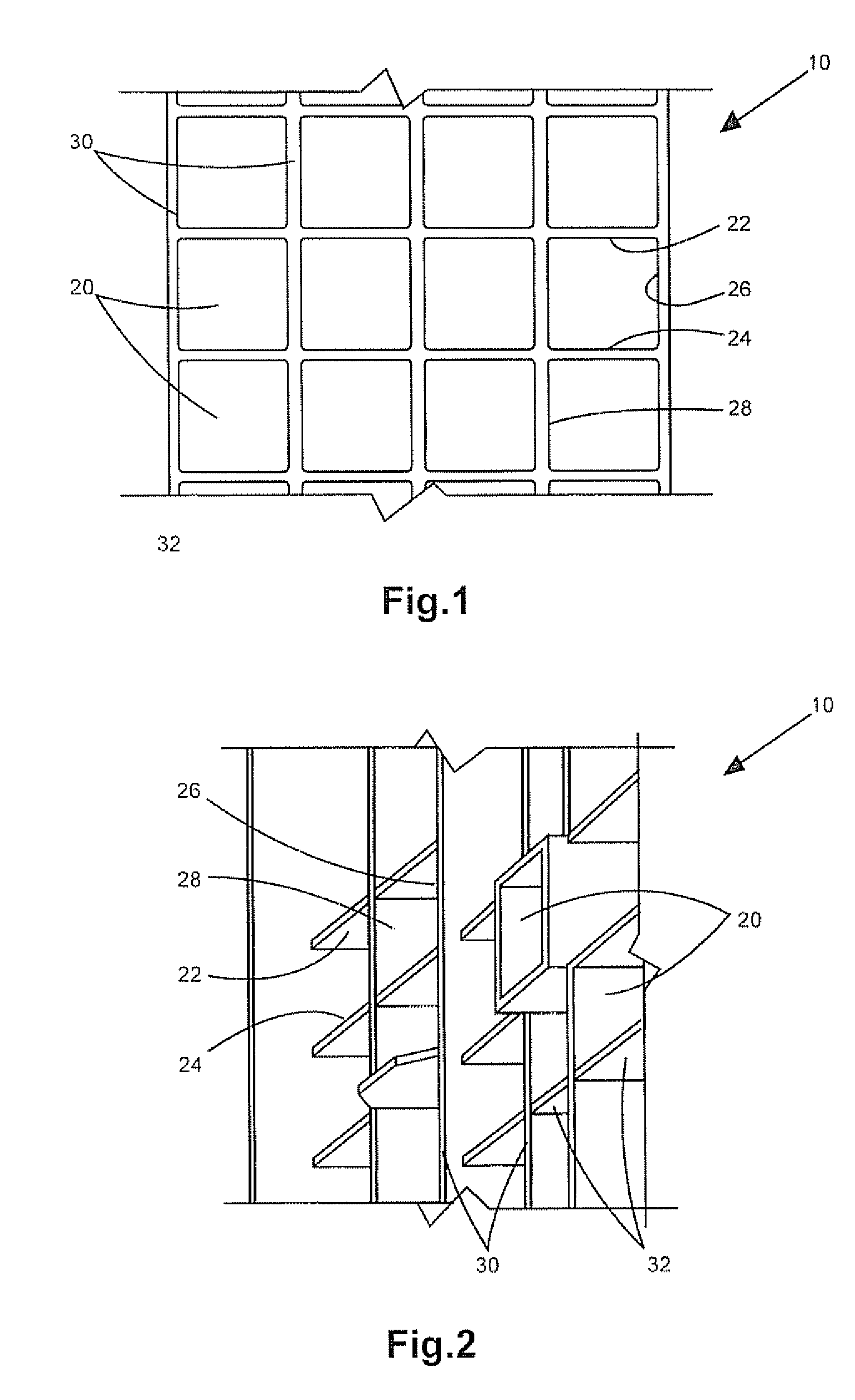
[0012]The embodiments described herein provide an apparatus and method for coupling multiple portions of structural walls of a multistory building such that the building will resist lateral loads caused by seismic actions, for example. In one embodiment, the apparatus is a structure comprising a first portion of stacked shear walls having a top end that is moveable between an unloaded position and a loaded position, and a bottom end that is substantially fixed; a second portion of stacked shear walls having a top end that is moveable between an unloaded position and a loaded position, and a bottom end that is substantially fixed; and a rigid member connecting the first top end to the second top end, wherein the rigid member couples the top ends in the unloaded and loaded positions.

[0013]In another embodiment, the apparatus is a structure comprising a first stack of poured-in-place concrete tunnels with each tunnel having a first longitudinal axis, and two vertical portions and a hor...


PUM


Abstract

An apparatus and method for coupling separate series or stacks of structural or shear walls of a multistory building are disclosed. The method comprises constructing a plurality of stacks of shear walls and attaching a rigid coupling member to the top of at least two of the stacks of shear walls between the stacks such that the walls are connected to the rigid coupling member and move together with the coupling member. The apparatus is a rigid coupling member, which may be a beam, such as an I-beam or rectangular beam, made from poured concrete and reinforcing steel. The coupling member may also be a wall of poured concrete and reinforcing steel. The attached rigid member acts to connect the tops of independent stacks of shear walls typically used to build multistory buildings, thereby creating a flexural moment at the top of the building that helps the building resist lateral loads.

Description

CROSS-REFERENCE TO RELATED APPLICATIONS[0001]The present application claims the benefit of U.S. Provisional Application Ser. No. 60 / 417,780 filed Oct. 11, 2002, entitled Structural Wall Coupling System, which is hereby incorporated herein by reference.STATEMENT REGARDING FEDERALLY SPONSORED RESEARCH OR DEVELOPMENT[0002]Not applicable.BACKGROUND OF THE INVENTION[0003]1. Field of the Invention[0004]The present invention relates to the process of constructing a building using shear walls, poured-in-place concrete tunnel forms, and other similar construction methods. More specifically, the present invention relates to beneficially distributing the seismic actions in a building constructed with stacks of shear walls or tunnel forms by coupling the shear walls at the top of the building.[0005]2. Background and Related Art[0006]In the construction of large residential complexes, high-rise buildings, and other multistory buildings, it is important to consider the axial, shear, and flexural ...

Claims


Application Information

Patent Timeline
Patent Type & Authority Patents(United States)
IPC IPC(8): E04B1/00E04B1/16E04H9/02
CPCE04H9/02E04B1/162
Inventor ENGLEKIRK, ROBERT E.GHODSI, AFSHINMAWBY, WALTER H.
Owner HIGHRISE CONCRETE SYST
Why Eureka
Try Eureka