Cord lock apparatus of window shade assembly

a technology of cord lock and window shade, which is applied in the direction of shutter/movable grille, door/window protective device, safety belt, etc., can solve the problem that the modular design of window shade parts cannot be fully achieved, and achieve the effect of convenient cord installation, flexibility and variety in use, and simple replacemen

Active Publication Date: 2009-10-06
NIEN MADE ENTERPRISE CO LTD
View PDF16 Cites 25 Cited by
  • Summary
  • Abstract
  • Description
  • Claims
  • Application Information

AI Technical Summary

Benefits of technology

[0012]The advantage of the present invention lies in that, both of the knurled roller and the engaging block are removable, which can ease the cords installation. Besides, it is simple to replace the engaging block size, and the cords in alternate diameters can be lockly gripped therein. Also, the modular components provide the flexibility and variety in use and the capability for mass production required in the commercial environment. Moreover, when adjusting the cords, the friction force imposed against the guide post where the cords are passed over can be substantially minimised through the utilization of the sliding bush structure, so the user can apply considerably less force to adjust the shade member, and further enhance the operative performance of the control cords.

Problems solved by technology

And thus, the manufacturers must produce engagement mechanisms 14 in a variety of specifications to properly accommodate the varying cords diameters in usage and so that the object of modular design on parts of the window shade cannot be fully achieved.

Method used


Image

  • Cord lock apparatus of window shade assembly
  • Cord lock apparatus of window shade assembly
  • Cord lock apparatus of window shade assembly

Examples


Embodiment Construction

[0025]The present invention is illustrated below more specifically with reference to the accompanying drawings and the embodiments.

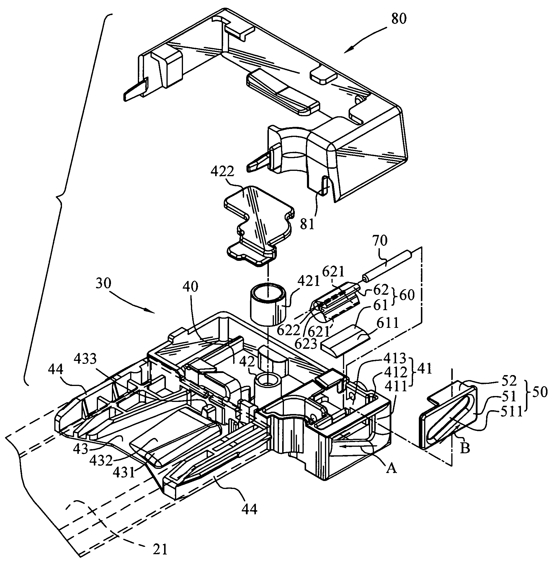
[0026]FIG. 3 is an exploded view of a cord lock apparatus in accordance with the present invention, FIG. 4 is a perspective front view of a window shade with the cords shown in the engaged and unlocked (dotted lines) positions in accordance with the present invention, and FIG. 5 is a schematic top plan view of the cord lock apparatus in accordance with the present invention. The cord lock apparatus 30 includes a base 40, a panel structure 50 and a cord gripping device 60. The panel structure 50 and the cord gripping device 60 are assembled on the base 40. The base 40 has an adjustable portion 41, a guide post 42, and a cord separating member 43. The cord separating member 43 is positioned relative to the adjustable portion 41 such that a turning angle is formed by the cord separating member 43 and the adjustable portion 41 with respect to the guide post ...


PUM


Abstract

A cord lock apparatus of a window shade is provided, which includes a base, a panel structure, and a cord gripping device. The base includes an adjustable portion allowing cords to pass through and a first-direction ascending opening is formed allowing the cords to be alternatively positioned. The panel structure having an insert plate and a second-direction ascending opening is provided allowing cords to pass through, when the cords are selectively positioned along the inclined surface, the panel structure is moved in a vertically upward or downward motion. The cord gripping device has an engaging block and a knurled roller, the engaging block is removably attached within the accommodation recess. The knurled roller is positioned near the top of the engaging block and a gap is formed therebetween, such that the knurled roller is frictionally locked with or released from the cords when the panel structure moves vertically downward or upward.

Description

BACKGROUND OF THE INVENTION[0001]1. Field of Invention[0002]The present invention relates to a cord lock apparatus for controlling the cords of a window shade, and particularly to a cord lock apparatus which is capable of altering the engaging gap space between the cords.[0003]2. Related Art[0004]Quite frequently, a cord lock apparatus of a window shade operated by a plurality of cords, such as a conventional blind or typically but not necessary a pleated shade, generally is mounted with a locking dog means. For example, U.S. Pat. No. 4,913,210 discloses a cord lock for window shades. FIG. 1 is a front perspective view of a cord lock in the prior art, and FIG. 2 is a sectional side view of FIG. 1. Referring to FIGS. 1 and 2, a base 12 is assembled on either one side of a generally U-shaped top rail 11 of a window shade 10, and at least two or a plurality of cords 13 pass through the base 12 from the lower portion and thence over an engagement mechanism 14. Then, the cords 13 are gui...

Claims


Application Information

Patent Timeline
Patent Type & Authority Patents(United States)
IPC IPC(8): E06B9/324
CPCE06B9/324Y10T24/394Y10T24/3944Y10T24/3947Y10T24/3942
Inventor NIEN, MINGWEN, YU-CHECHANG, CHIH-YAOPON, DAVIDREN, JUDKINS
Owner NIEN MADE ENTERPRISE CO LTD
Why Eureka
Try Eureka