Discharge determination device and method

a technology of discharge determination device and discharge determination method, which is applied in the direction of printing, inking apparatus, other printing apparatus, etc., can solve the problems of inability to discharge ink from the nozzl

Inactive Publication Date: 2009-10-06
FUJIFILM CORP
View PDF31 Cites 11 Cited by
  • Summary
  • Abstract
  • Description
  • Claims
  • Application Information

AI Technical Summary

Benefits of technology

[0010]The present invention has been contrived in view of the foregoing circumstances, an object thereof being to provide a discharge determination device or determination method suitable for accurately judging whether or not a discharge failure has occurred, and for efficiently determining a plurality of nozzles in a long head, or the like, by determining the level of the ink pressure in the pressure chambers or in the vicinity of same, with respect to the pressure generated by the actuators.
[0012]According to the present invention, a composition is adopted which determines pressure change in the liquid by means of displacement of a film member disposed at the face of the pressure chamber, and hence evaluates how the pressure generated by the actuator is transmitted to the liquid. Therefore, from this determination information, it is possible to judge not only whether or not liquid is present, but also whether or not an air bubble which would cause discharge failure due to pressure loss is present. Consequently, it can be judged whether or not the pressure chamber is in a state producing a discharge failure. Furthermore, in order to prevent the displacement of the film member according to the present invention from affecting the discharge of liquid, the reduction in discharge performance due to addition of the pressure determination device is reduced to a minimum.
[0025]By adding a displacement restriction device, it is possible to achieve a non-linear response of the film member whereby it is displaced rapidly in the initial phase of pressure change but is not displaced further once the required displacement has been obtained. Therefore, high-precision pressure determination can be achieved without significantly affecting liquid discharge.
[0032]Preferably, the supply flow channel is formed in such a manner that a cross-sectional area of the supply flow channel reduces as the supply flow channel progresses in a downstream direction.
[0033]By adopting a composition in which the cross-sectional area of the flow channel reduces gradually in the downstream direction of the liquid flow, the flow rate becomes faster toward the downstream side and the possibility of removing air bubbles is increased. Furthermore, although the distance from the film member increases, the further the channel extends downstream, by making the cross-sectional area of the flow channel reduce gradually, it is possible to reduce attenuation of pressure waves and hence increase determination accuracy.
[0041]According to the present invention, since a pressure determination device using a film member is provided in at least one of a pressure chamber and a supply side flow channel connected to pressure chambers, the pressure change in the liquid being determined by means of this pressure determination device, then on the basis of this determination information, it is possible to judge not only the presence or absence of liquid, but also whether or not a state producing a discharge failure has occurred. Moreover, according to one mode of the present invention, since the pressure loss caused by displacement of the film member is designed so as to be within a range that does not affect discharge driving by the actuators or replenishment of the liquid, then it is possible to determine discharge during driving of the actuators, without reducing discharge functions.

Problems solved by technology

In an apparatus of this kind, discharge errors may arise, namely, ink may cease to be discharged from the nozzles, or the amount of ink discharged (the dot size deposited on the recording medium) or the position at which the ink is deposited may become defective, as a result of increase in the viscosity of the ink, infiltration of air bubbles into the ink, or the like.
Since the air bubbles absorb the pressure by changing volume, then the pressure generated by the actuators for ink discharge cannot be used efficiently in order to discharge the ink.
However, these publications do not disclose the acquisition of a determination signal during pressurization.
Supposing that it were attempted to determine the status during pressurization by means of the composition described in Japanese Patent Application Publication No. 5-131644 or 11-286124, the circuit composition would become extremely complicated.
However, it does not determine ink discharge errors.

Method used


Image

  • Discharge determination device and method
  • Discharge determination device and method
  • Discharge determination device and method

Examples


Embodiment Construction

General Configuration of Inkjet Recording Apparatus (Printer)

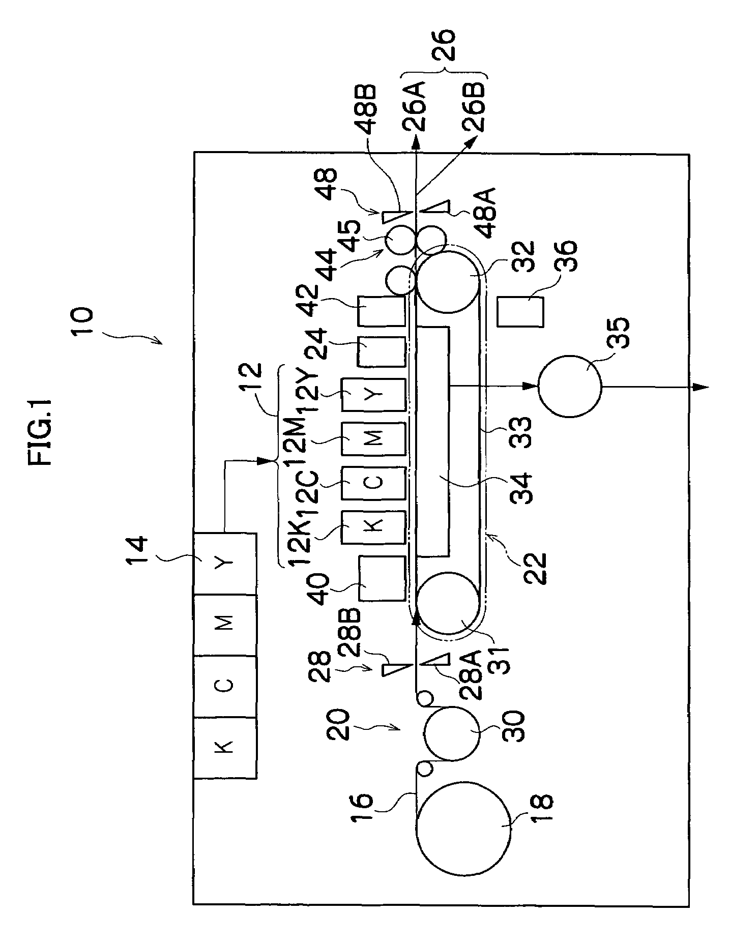
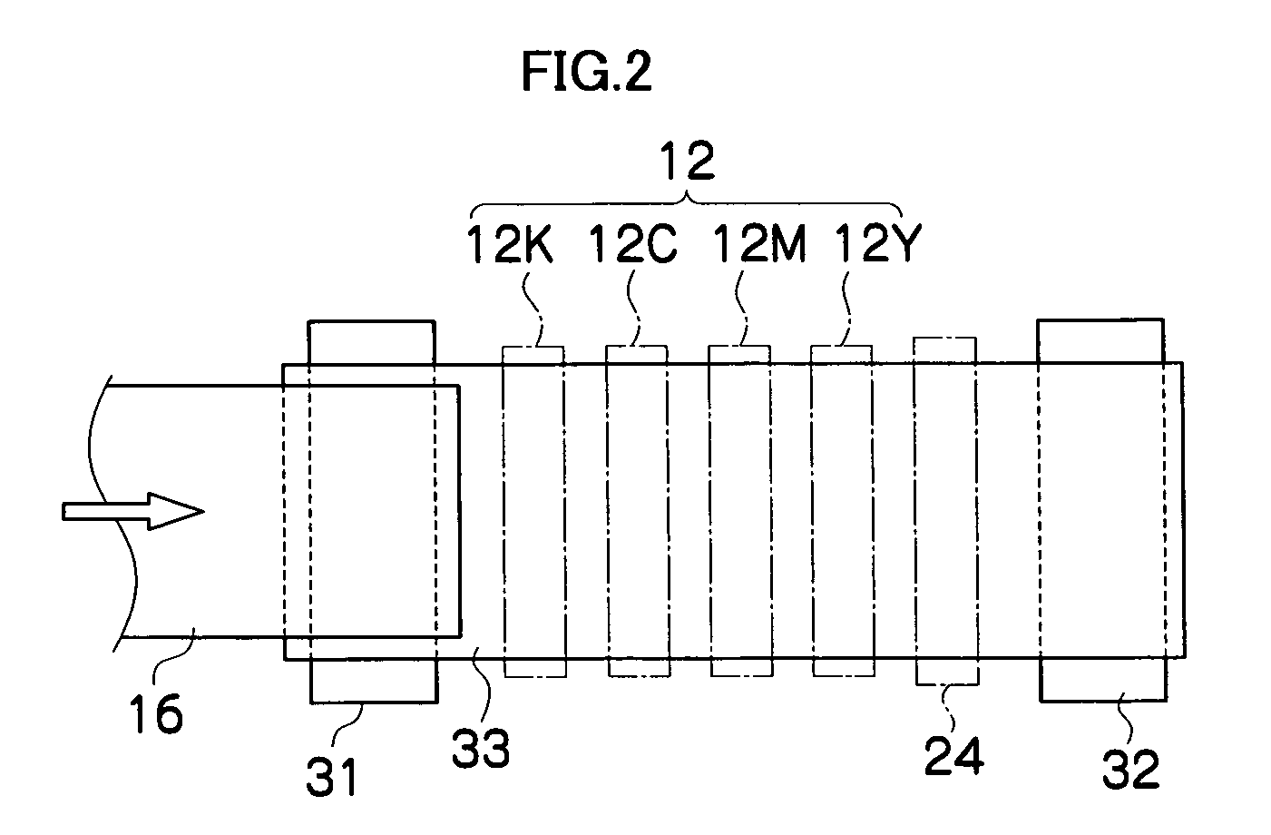
[0061]FIG. 1 is a general schematic drawing of an inkjet recording apparatus according to an embodiment of the present invention. As shown in FIG. 1, the inkjet recording apparatus 10 comprises: a printing unit 12 having a plurality of print heads 12K, 12C, 12M, and 12Y for ink colors of black (K), cyan (C), magenta (M), and yellow (Y), respectively; an ink storing and loading unit 14 for storing inks of K, C, M and Y to be supplied to the print heads 12K, 12C, 12M, and 12Y; a paper supply unit 18 for supplying recording paper 16; a decurling unit 20 for removing curl in the recording paper 16; a suction belt conveyance unit 22 disposed facing the nozzle face (ink-droplet ejection face) of the print unit 12, for conveying the recording paper 16 while keeping the recording paper 16 flat; and a paper output unit 26 for outputting image-printed recording paper (printed matter) to the exterior.

[0062]The ink storing and loading...


PUM


Abstract

The discharge determination device which determines discharge status in a droplet discharge apparatus comprising: a nozzle which discharges a droplet of liquid; a pressure chamber which is connected to the nozzle and stores the liquid to be discharged from the nozzle; a supply flow channel which supplies the liquid to the pressure chamber and is connected to the pressure chamber; and an actuator which causes the droplet to be discharged from the nozzle by causing at least a portion of the pressure chamber to deform and thereby applies a pressure change to the liquid inside the pressure chamber, the discharge determination device comprises: a pressure determination device which is disposed inside the pressure chamber and includes a film member forming a portion of a face constituting the pressure chamber, the film member being displaceable in accordance with pressure change in the liquid inside the pressure chamber, the pressure determination device outputting a determination signal in accordance with displacement of the film member; and a discharge status judging device which judges the discharge status of the nozzle according to the determination signal obtained from the pressure determination device in accordance with driving of the actuator.

Description

BACKGROUND OF THE INVENTION[0001]1. Field of the Invention[0002]The present invention relates to a discharge determination device and method, and more specifically to a discharge determination device and method suitable for determining discharge errors in a discharge head having a plurality of droplet discharge ports (nozzles).[0003]2. Description of the Related Art[0004]An inkjet type recording apparatus forms images on a recording medium by discharging ink from nozzles while moving a print head having a plurality of nozzles and a recording medium relatively with respect to each other. In an apparatus of this kind, discharge errors may arise, namely, ink may cease to be discharged from the nozzles, or the amount of ink discharged (the dot size deposited on the recording medium) or the position at which the ink is deposited may become defective, as a result of increase in the viscosity of the ink, infiltration of air bubbles into the ink, or the like. Therefore, technology for deter...

Claims


Application Information

Patent Timeline
Patent Type & Authority Patents(United States)
IPC IPC(8): B41J29/393B41J2/19B41J2/45B41J2/045
CPCB41J2/0451B41J2/04588B41J2/04581B41J2/14233B41J2002/14266B41J2002/14354B41J2002/14459B41J2202/20
Inventor NAGASHIMA, KANJI
Owner FUJIFILM CORP
Why Eureka
Try Eureka