Shelving illumination element

a technology of illumination element and transparent surface, which is applied in the direction of lighting, heating apparatus, protection devices, etc., can solve the problem that none of these inventions, however, describes an illumination element with an illuminated transparent visible surface, and achieve the highest possible level of legibility of the transparent light surfa

Inactive Publication Date: 2009-10-06
GESA FORM FUNKTION DISPLAYBAU
View PDF9 Cites 20 Cited by
  • Summary
  • Abstract
  • Description
  • Claims
  • Application Information

AI Technical Summary

Benefits of technology

[0008]By means of the disposal of the light source and the luminous means in a region which does not permit a direct view of the luminous means from outside, the even emergence of light is achieved without the necessity for a deep construction.
[0011]The advantages achieved with the invention consist therein that a surface-luminous illumination unit is provided which permits the products in the respective cabinet to be labelled and / or indicated in a manner that advertises them effectively in a highly compact construction. In addition, the surface-luminous illumination unit can be used as a decorative structural element.
[0012]Due to the illumination effect, it is possible to place product information or promotional advertising of the respective products visibly near the relevant products. A further advantage of the surface-luminous illumination unit is that the greatest possible level of legibility of the transparent light surface is ensured, even in poor lighting conditions.

Problems solved by technology

None of these inventions, however, describes an illumination element with an illuminated transparent visible surface which is suitable for accommodating lettering, depictions, coloured fields or the like.

Method used


Image

  • Shelving illumination element
  • Shelving illumination element
  • Shelving illumination element

Examples


Embodiment Construction

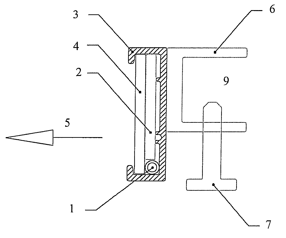
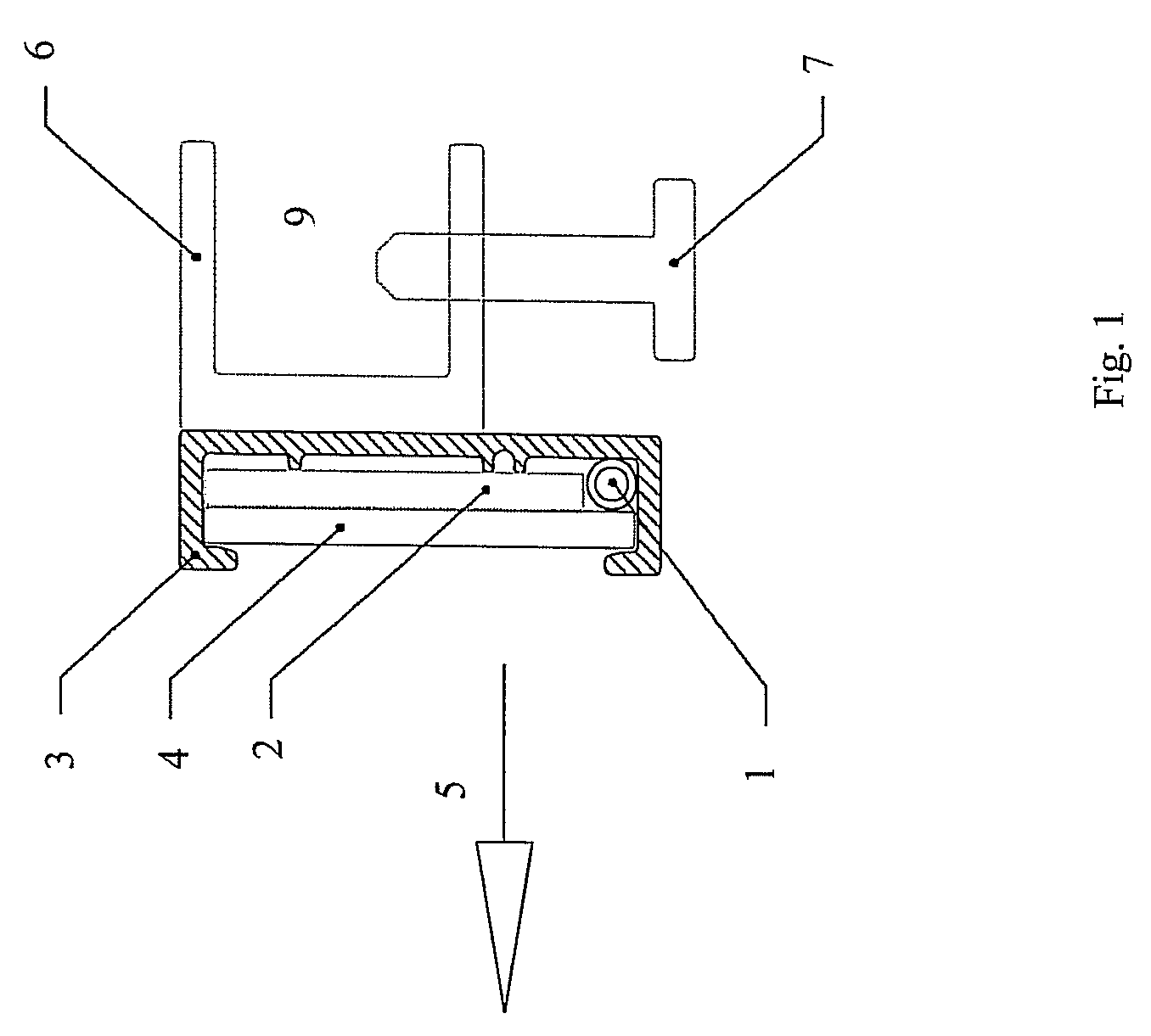
[0018]FIG. 1 shows the illumination element according to the invention in a schematic representation. The light source 1 is located in a region of the illumination element which does not permit a direct line of sight to an observer standing in front of the light emitting zone 5. The light emitted from the light source passes through the light-conducting luminous body 2 to the transparent visible surface 4. By means of special doping of the luminous body 2, the light which is radiated into the luminous body at the narrow side surface is deflected within the luminous body, so that the light emerges from the front side of the luminous body.

[0019]In the preferred embodiment, a transparent visible surface 4 (diffusion screen) which has a scattering effect and makes the emerging light appear more diffuse is disposed in front of the luminous body.

[0020]The preferably tubular luminous means 1 is disposed in a recess which is shielded from behind and below by the housing or support profile 3...


PUM


Abstract

Product cabinet having an illumination element, wherein the illumination element is fastened to the product cabinet and further comprises:a light-conducting luminous body which has a planar front side from which light emerges and which has a side surface into which light is fed, wherein the luminous body is configured so that the light entering laterally is deflected within the luminous body to the front side, so that it emerges there; and at least one light source, which emits light onto the side surface.

Description

ILLUMINATION ELEMENT[0001]The invention relates to an illumination element comprising at least one light source, a light-conducting luminous body of planar design and a housing, wherein the light source is installed in a light emitting zone which is adjoined on at least one side by a light-conducting luminous body which accepts the light laterally and emits it forwardly.FIELD OF THE INVENTION[0002]Illumination elements of many designs are known. The German laid-open document DE 42 20 727 A1 discloses a surface-luminous illumination unit which is designed as a compact unit and emits a glare-free light, in order to illuminate effectively the objects to be illuminated. The surface-luminous illumination unit therein described is constructed from light-transmitting luminous panels which are disposed in layers above one another such that the sides of the luminous panels into which the light enters lie on a level with one another, whereas the other sides from which the light emerges are di...

Claims


Application Information

Patent Timeline
Patent Type & Authority Patents(United States)
IPC IPC(8): F21V17/14
CPCA47B97/00G02B6/0088A47F11/10
Inventor MISOF, TIMM
Owner GESA FORM FUNKTION DISPLAYBAU
Why Eureka
Try Eureka