Disc Brake And Brake Actuation Mechanism For A Disc Brake

a disc brake and actuation mechanism technology, applied in the direction of actuators, slack adjusters, braking elements, etc., can solve the problems of not always being guaranteed, uncertain, small risk, etc., and achieve the effect of more freedom

Active Publication Date: 2017-04-20
HALDEX BRAKE PROD AB
View PDF2 Cites 4 Cited by
  • Summary
  • Abstract
  • Description
  • Claims
  • Application Information

AI Technical Summary

Benefits of technology

[0045]The embodiment having the additional spring element has the advantage that more freedom is provided for the design of the other compone...

Problems solved by technology

Under certain circumstances a certain, however small risk exists with respect to the above-mentioned brake actuation mechanism, in that the adjustment mechanism and the thrust piece, respectively, could nevertheless move away from the brake disc, if no more brake force will be transmitted.
It can thus not always be guaranteed, that the sprag spring will always slip and decouple the internal holding sleeve from the hollow shaft upon release of the brake.
Under certain circumstances a further problem could exist in that single frictional contacts between the single components of the brake actuation mechanism as such and the resulting sum of all these frictional contacts, respectively, will be sufficient in order to cause a torque upon release of the brake, i.e. in case no more clamping force is transmitted through the brake actuation mechanism and through its single components and thus also through the adjustment mechanism, which torque will be large enough to apply a rotation onto components, which components shall not rotate upon release of the brake, wherein under certain circumstances this rotation as transmitted onto such components could effect a counter-rotation of the adjustment mechanism and thus a return ...

Method used


Image

  • Disc Brake And Brake Actuation Mechanism For A Disc Brake
  • Disc Brake And Brake Actuation Mechanism For A Disc Brake
  • Disc Brake And Brake Actuation Mechanism For A Disc Brake

Examples


first embodiment

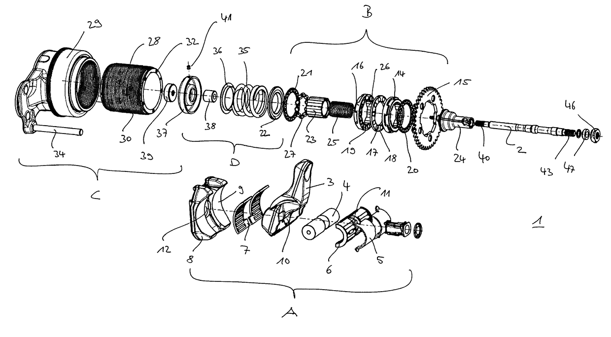
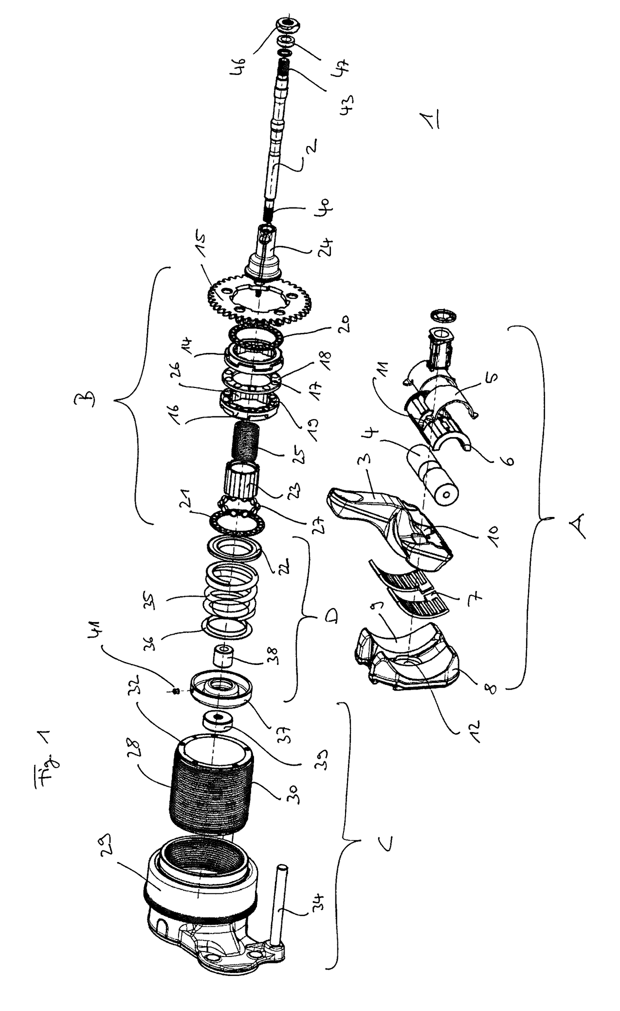
[0064]In an explosive view FIG. 1 shows a brake actuation mechanism 1 with its single pieces according to the invention.

[0065]The brake actuation mechanism 1 substantially consists of an amplification mechanism A, which introduces an actuator force resulting from a hydraulic, pneumatic or electro-mechanical (or a combination thereof) actuator (not shown herein) as a clamping force into the brake actuation mechanism 1 and thereby amplifies the same according to a constructively determined transmission ratio, of an adjustment mechanism B, which serves for compensating the brake pad / lining wear, of a thrust element C, which transmits the amplified clamping force onto the brake disc, and of a return mechanism D, in order to reset the brake actuation mechanism 1 into its starting position, if no more brake force will be applied by the actuator, which is placed outside of the housing of the brake caliper.

[0066]A crucial feature of the disc brake and the brake actuation mechanism according...

second embodiment

[0099]In the FIGS. 4 to 6c a brake actuation mechanism 48 in a second embodiment according to the invention is shown.

[0100]The structure of this brake actuation mechanism 48 comprises a configuration of the amplification mechanism A, of the adjustment mechanism B, of the thrust element C and of the return mechanism D, which is identical to the first embodiment. Same reference numerals are used for the same elements.

[0101]This brake actuation mechanism 48, however, differs with respect to the configuration of the device for creating a resistant torque for the threaded engagement between the adjustment spindle 28 and the thrust piece 29 according to the invention.

[0102]At the side of the brake disc a leaf-like spring element 49 is provided which attaches to an abutment cup 50, when seen from the outside of the brake disc.

[0103]As with the embodiment as described, above the abutment cup 50 will be axially positioned on the rod 2 by means of the distance ring 38 and the fixation nut 39....


PUM


Abstract

A disc brake including a brake caliper and a brake actuation mechanism having an amplification mechanism for introducing a clamping force, an adjustment mechanism for compensating a lining wear having a torque clutch, a thrust element for transmitting the clamping force onto the brake disc, wherein the thrust element includes an adjustment spindle, and a return mechanism, wherein the amplification mechanism, the adjustment mechanism, the thrust element and the return mechanism are mounted in a functional interacting manner in the brake caliper by way of a rod. The disc brake is further provided with at least one device, which is configured to exert a defined resistant torque on the rotation of the adjustment spindle.

Description

FIELD OF THE INVENTION[0001]The present invention relates to a disc brake, in particular for an utility vehicle, and to a brake actuation mechanism for a disc brake.BACKGROUND OF THE INVENTION[0002]In this connection the invention shall include disc brakes which either comprise a sliding caliper or a fixed caliper, and which overlap one or more brake discs. Mainly but not exclusively the invention relates to disc brakes with lining sections of the spot-type.[0003]Disc brakes, in particular for heavy load trucks, with different configurations are known both with respect to the type of the brake actuation mechanism, with respect to the way of the transmission of the braking force onto one or several brake discs and with respect to the type of the adjustment for compensating the wear of the brake pads and brake linings, respectively.[0004]For example, one specific embodiment of a brake actuation mechanism, which is embodied in disc brakes, is known from International Application WO 201...

Claims


Application Information

Patent Timeline
IPC IPC(8): F16D65/56F16D65/18
CPCF16D65/567F16D65/18F16D2121/14F16D2125/28F16D2125/40F16D55/226F16D55/227F16D65/0043F16D65/52F16D66/026F16D2129/04F16D2250/0084
Inventor SANDBERG, STEFAN
Owner HALDEX BRAKE PROD AB
Why Eureka
Try Eureka