Compact MIMO antenna system based on connecting line

A kind of antenna system, technology of connecting line

Pending Publication Date: 2020-03-27
朴海燕
View PDF0 Cites 4 Cited by
  • Summary
  • Abstract
  • Description
  • Claims
  • Application Information

AI Technical Summary

Problems solved by technology

However, the size of the antenna required by this method is large, and it is difficult to realize the integration and miniaturization of the MIMO antenna system.
[0007] The above-mentioned existing technologies either cannot realize a compact MIMO system, or have a relatively complex decoupling structure, or have great application limitations, or have a large antenna size

Method used


Image

  • Compact MIMO antenna system based on connecting line
  • Compact MIMO antenna system based on connecting line
  • Compact MIMO antenna system based on connecting line

Examples


Embodiment 1

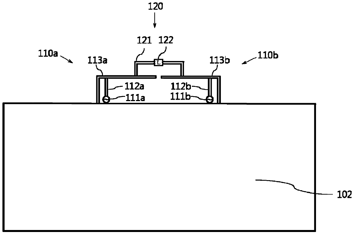
[0043] FIG. 1 shows a schematic structural diagram of a cable-based compact MIMO antenna system according to Embodiment 1 of the present invention.

[0044] As shown in FIG. 1, a compact MIMO antenna system based on connecting wires includes a ground plane 102, a first antenna 110a, a second antenna 110b, and connecting wires 120 arranged outside the first antenna 110a and the second antenna 110b, so The outer end of the first antenna 110a and the outer end of the second antenna 110b are respectively connected to the ground plate 102, and one end of the connecting line 120 is connected to the non-end of the first antenna 110a and the other end of the connecting line 120 The terminal is connected to the non-terminal of the second antenna 110b. It should be understood that the terminus referred to in the embodiments of the present invention refers to the position of one end of the line, the other terminus refers to the position of the end opposite to the terminus, and the connec...

Embodiment 2

[0056] Fig. 2 is a schematic structural diagram of a compact MIMO antenna system based on connecting wires in Embodiment 2 of the present invention.

[0057] As shown in FIG. 2 , a compact MIMO antenna system based on connecting wires includes a ground plane 102, a clearance area 204, a first antenna 210a, a second antenna 210b, and connections configured outside the first antenna 210a and the second antenna 210b. Line 220, the outer end of the first antenna 210a and the outer end of the second antenna 210b are respectively connected to the ground plate 102, one end of the connecting line 220 is connected to the non-end of the first antenna 210a and the connecting line The other end of the antenna 220 is connected to a non-end of the second antenna 210b. Both the first antenna 210 a and the second antenna 210 b are disposed in the clearance area 204 . The clearance area 204 is a groove hollowed out on the side of the grounding plate 102 .

[0058] Such as Figure 2a As show...


PUM


Abstract

The invention discloses a compact MIMO antenna system based on a connecting line. The system comprises a grounding plate, a first antenna, a second antenna, and a connecting line arranged outside thefirst antenna and the second antenna. The tail end of the outer side of the first antenna and the tail end of the outer side of the second antenna are connected with the grounding plate, one tail endof the connecting wire is connected with the non-tail end of the first antenna, and the other tail end of the connecting wire is connected with the non-tail end of the second antenna. The compact MIMOantenna system based on the connecting line has the advantages of being compact in antenna structure, small in antenna unit size, short in unit distance and the like, high integration, high compactness and high isolation are achieved, and the compact MIMO antenna system is compatible with MIMO antenna systems of various antenna types. The method can be applied to various wireless communication equipment, and is especially suitable for application of large-scale arrays in terminal equipment.

Description

technical field [0001] The invention relates to the technical field of communication antennas, and specifically proposes a connection line-based compact MIMO antenna system decoupling technology, which can be used for various wireless communication devices. Background technique [0002] Antennas have become an essential device in various wireless devices to transmit and receive electromagnetic wave signals. MIMO (Multiple-Input Multiple-Output) technology uses multiple antenna devices to transmit and receive at the same time, which can greatly increase the wireless transmission rate without increasing the transmission power or operating spectrum. It is the core technology of the fourth-generation mobile communication and fifth-generation communication systems one. In order to ensure excellent MIMO characteristics, it is necessary to achieve high isolation or low coupling between antennas to reduce the correlation between antennas. However, due to the limited space of moder...

Claims


Application Information

Patent Timeline
Patent Type & Authority Applications(China)
IPC IPC(8): H01Q1/36H01Q1/48H01Q1/50H01Q1/52H01Q21/00
CPCH01Q1/36H01Q1/48H01Q1/50H01Q1/521H01Q21/0006
Inventor 曲龙跃朴海燕
Owner 朴海燕
Why Eureka
Try Eureka