Surface-coated cutting tool with hard coating layer having excellent abrasion resistance

a cutting tool and hard coating technology, applied in the field of surface coating cutting tools, can solve the problems of plastic deformation, easy cracking in the hard coating layer, and the 3/sub>layer and the conventional alzro layer of the upper layer of the hard coating layer do not meet the high-temperature strength and surface properties, so as to improve the strength of crystal grains, improve the peeling resistance, and improve the loss resistance

Active Publication Date: 2009-10-06
MITSUBISHI MATERIALS CORP
View PDF9 Cites 30 Cited by
  • Summary
  • Abstract
  • Description
  • Claims
  • Application Information

AI Technical Summary

Benefits of technology

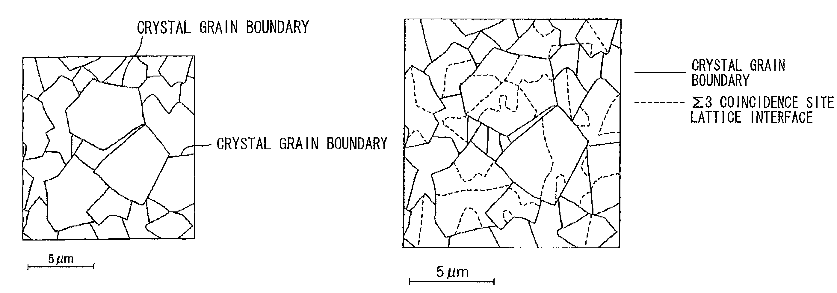
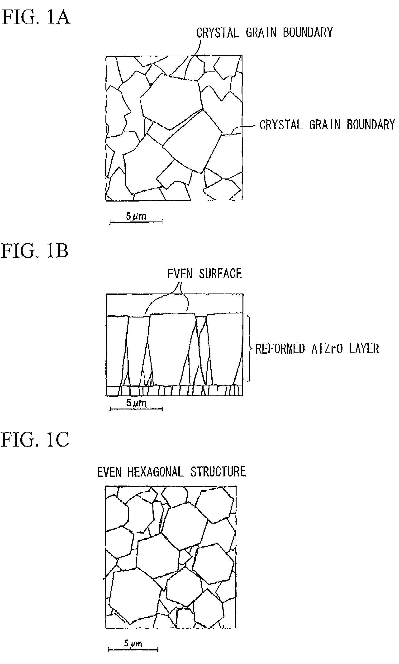
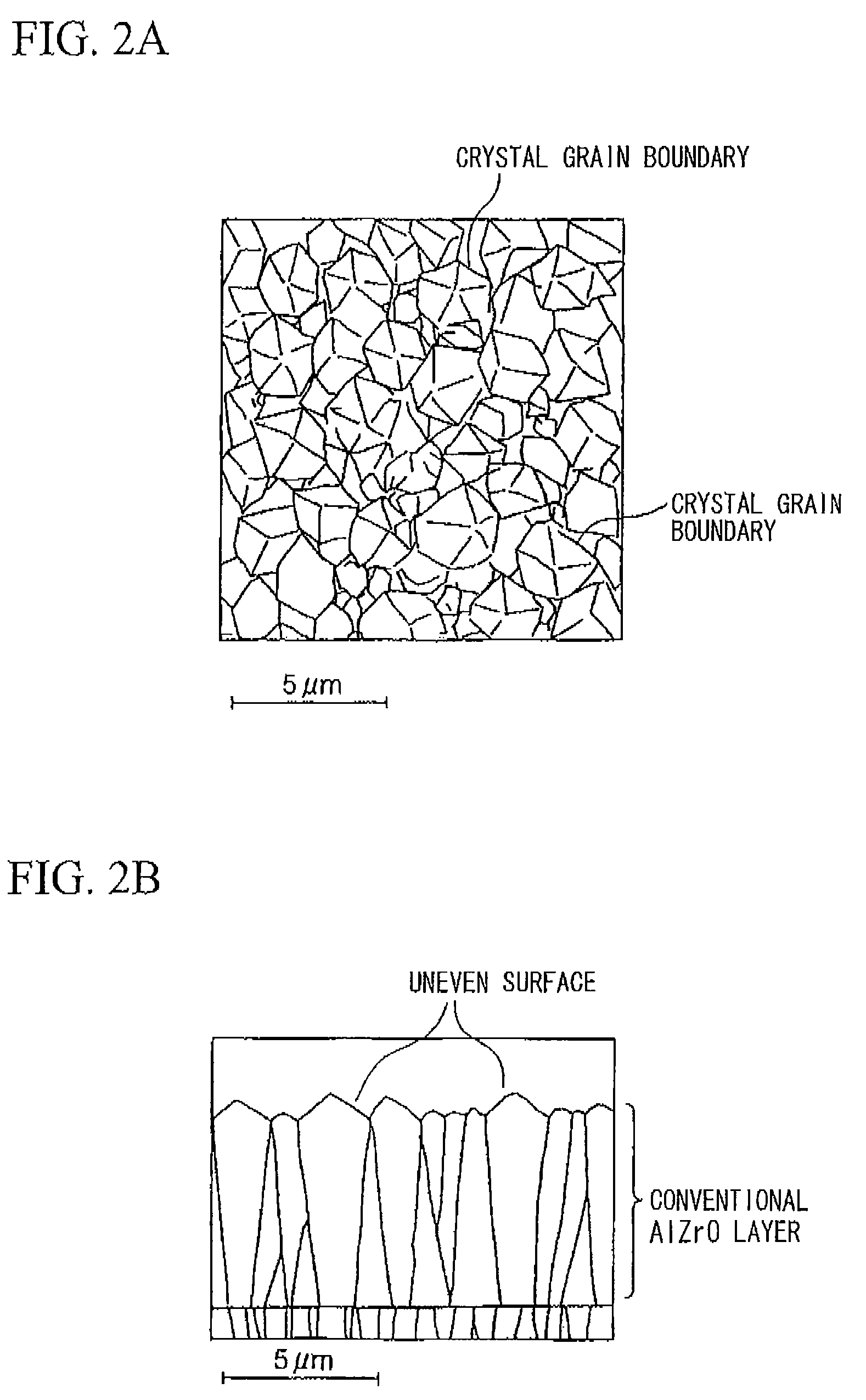
[0032](d) In the upper layer formed of the reformed AlZrO layer formed under the chemical vapor deposition conditions (hereinafter, referred to as “condition of the invention”) of the first and second steps described in the (b), the crystal face of the surface has the same orientation as the crystal face (for example, (0001)) in the plane perpendicular to the thickness direction. Accordingly, (as viewed in the plane parallel to the thickness direction), the layer surface had an almost even plate shape and exhibited excellent chipping resistance due to the surface structure. Since the strength in the crystal grains can be enhanced due to the existence of the Σ3 coincidence site lattice interface in the crystal grains having the even polygonal elongate shape, more excellent high-temperature hardness, high-temperature strength, and surface structure were obtained than those of the conventional AlZrO layer of the conventional coated tool. As a result, the reformed AlZrO layer according to the invention exhibits excellent abrasion resistance for a long time without causing chipping, breakage, and peeling during a high-speed heavy cutting work in which a heavy load is applied to cutting edges with high-temperature heat.
[0064]As described above, in the coated tool according to the invention, the reformed AlZrO layer as the upper layer has a structure including even polygonal (including a hexagonal shape) elongate crystal grains with surface evenness. The Σ3 coincidence site lattice interface is formed in the crystal grains to enhance the strength of the crystal grains. Accordingly, in comparison with the conventional coated tool including the conventional AlZrO layer having the uneven polygonal elongate crystal grains and a small number of Σ3 coincidence site lattice interface in the crystal grains as the upper layer, excellent high-temperature strength and excellent abrasion resistance are accomplished in addition to the high-temperature hardness and the heat resistance of the conventional AlZrO layer. As a result, the hard-coating layer exhibits excellent chipping resistance, excellent breakage resistance, excellent peeling resistance, and excellent abrasion resistance during high-speed heavy cutting work on steel, cast iron, etc. in which high-temperature heat is emitted and a heavy load is applied to the cutting edges, thereby elongating the usable lifetime.

Problems solved by technology

However, the α-type Al2O3 layer and the conventional AlZrO layer of the upper layer of the hard-coating layer do not satisfy the high-temperature strength and the surface properties.
Accordingly, when the conventional cutting tool is used in heavy cutting work under the condition of higher speed, chipping easily occurs in the hard-coating layer and plastic deformation and uneven abrasion also easily occur.
Actually, the abrasion resistance is deteriorated for these reasons, thereby shortening the usable life thereof.

Method used


Image

  • Surface-coated cutting tool with hard coating layer having excellent abrasion resistance
  • Surface-coated cutting tool with hard coating layer having excellent abrasion resistance
  • Surface-coated cutting tool with hard coating layer having excellent abrasion resistance

Examples


examples

[0069]The following powders, each having a mean particle size in a range of 2 to 4 μm, were prepared as raw materials: WC powder, TiC powder, ZrC powder, VC powder, TaC powder, NbC powder, Cr3C2 powder, TiN powder, TaN powder and Co powder. These raw powders were compounded with each other based on the compounding compositions shown in Table 1. Wax was added thereto, and the resultant was mixed in an acetone solution for 24 hours using a ball mill and was dried under a reduced pressure. Thereafter, the resultant powder mixture was press-formed in a green compact having a predetermined shape at a pressure of 98 MPa. The green compact was then sintered in a vacuum under the following conditions: a pressure of 5 Pa, a predetermined temperature in a range of 1370 to 1470° C., and a holding duration of 1 hour. After sintering, cutting edges were subjected to honing with R of 0.07 mm, thereby manufacturing tool substrates A to E made of WC-based cemented carbide and having throwaway tip s...


PUM

PropertyMeasurementUnit
thicknessaaaaaaaaaa
thicknessaaaaaaaaaa
thicknessaaaaaaaaaa

Abstract

In a surface-coated cutting tool, (a) a Ti compound layer as a lower layer and (b) an α-type Al2O3 layer as an upper layer having a crystal grain structure of an even polygonal shape (including an even hexagonal shape) and an elongate shape and containing Zr are deposited on the surface of a tool substrate. In the surface-coated cutting tool, the above mentioned crystal grains of which insides are divided by at least one crystal lattice interface with the constituent atom covalent lattice point type expressed by Σ3 occupying 60% or more as an area ratio in the crystal grains of the upper layer.

Description

BACKGROUND OF THE INVENTION[0001]1. Field of the Invention[0002]The present invention relates to a surface-coated cutting tool (hereinafter, referred to as a coated tool) of which a hard-coating layer exhibits excellent abrasion resistance for a long time without becoming chipped during high-speed heavy cutting of steel, cast iron, etc. in which high-temperature heat is emitted and a heavy load is applied to the cutting edges.[0003]Priority is claimed on Japanese Patent Application No. 2007-338865, filed Dec. 28, 2007, and Japanese Patent Application No. 2008-160053, filed Jun. 19, 2008, the content of which are incorporated herein by reference.[0004]2. Description of Related Art[0005]In the past, a coated tool was known, which is generally formed by coating a surface of a substrate (hereinafter, generally referred to as a tool substrate) made of tungsten carbide (hereinafter, referred to as WC)-based cemented carbide or titanium carbonitride (hereinafter, referred to as TiCN)-based...

Claims


Application Information

Patent Timeline
Patent Type & Authority Patents(United States)
IPC IPC(8): B23B27/14B23B27/00B24D99/00
CPCC23C16/0272C23C16/403C23C30/005Y10T428/24942Y10T407/23Y10T407/27
Inventor TOMITA, KOUHEINISHIYAMA, MICHIYASUOSADA, AKIRANAKAMURA, EIJI
Owner MITSUBISHI MATERIALS CORP
Why Eureka
Try Eureka