Connector with terminal motion reduction

a technology of connecting rods and terminals, applied in the direction of couplings/cases, coupling device connections, coupling protection earth/shielding arrangements, etc., can solve the problems of electrical connection dielectric failure, possible cracking of plastic connector parts, vibration and other motion of electrical connectors in vehicles, etc., to reduce vibration and other motion of terminals caused by vehicle movement, the effect of efficiently sealing the assembly

Inactive Publication Date: 2009-10-06
YAZAKI NORTH AMERICA
View PDF26 Cites 67 Cited by
  • Summary
  • Abstract
  • Description
  • Claims
  • Application Information

AI Technical Summary

Benefits of technology

[0006]Another object of the invention is to ease the assembly process by including retention features to hold the terminals in position as the motion reduction features are assembled around the terminals.
[0007]A further object of the invention is to efficiently seal the assembly around the motion reduction features to protect the terminal wire connections without the use of epoxies or resins.
[0008]In carrying out this invention in the illustrative embodiment thereof, the motion of the right-angle electrical terminals within a high-voltage connector assembly is limited by resilient cradle-like members supporting the terminals. The terminals are placed in the cradle-like members in a first housing part. A recessed ledge surrounds the cradle-like members. A retention feature in the first housing part comprises a groove on each side of the terminal for receiving protrusions jutting out from the terminal. A deflectable projection in each groove snaps over the terminal protrusions to lock the terminals in position when the terminals are fully seated. The terminals are prevented from being pulled at an angle ninety degrees from the vertical orientation or direction of the grooves.
[0009]A second housing part has additional cradle-like members for alignment with the cradle-like members in the first part. The cradle-like members of the second part extend from a raised portion of a base of the second part. The raised portion is sized and arranged to fit against a seal placed on the recessed ledge of the first housing part when the second housing part is assembled on the first housing part. Simultaneously, the wire-connect segments of the terminals are clamped between the cradle-like members of both housing parts as the parts are locked together. Vibration and other motion of the terminals caused by vehicle movement are reduced or eliminated.

Problems solved by technology

Electrical connectors in vehicles are subject to vibration and other motion caused by vehicle movement.
Cracking in the plastic connector parts and dielectric failure of the electrical connection are possible if the motion is not controlled.
The resin requires preparation time, special equipment and handling, and curing time that can take a few hours.
This significantly increases the assembly time and cost of the connector.
The terminals are difficult or impossible to remove from the connector after the resin is cured.

Method used


Image

  • Connector with terminal motion reduction
  • Connector with terminal motion reduction
  • Connector with terminal motion reduction

Examples


Embodiment Construction

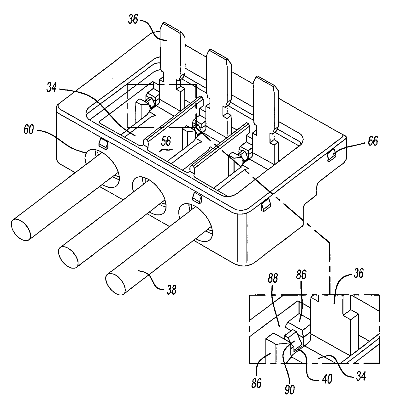
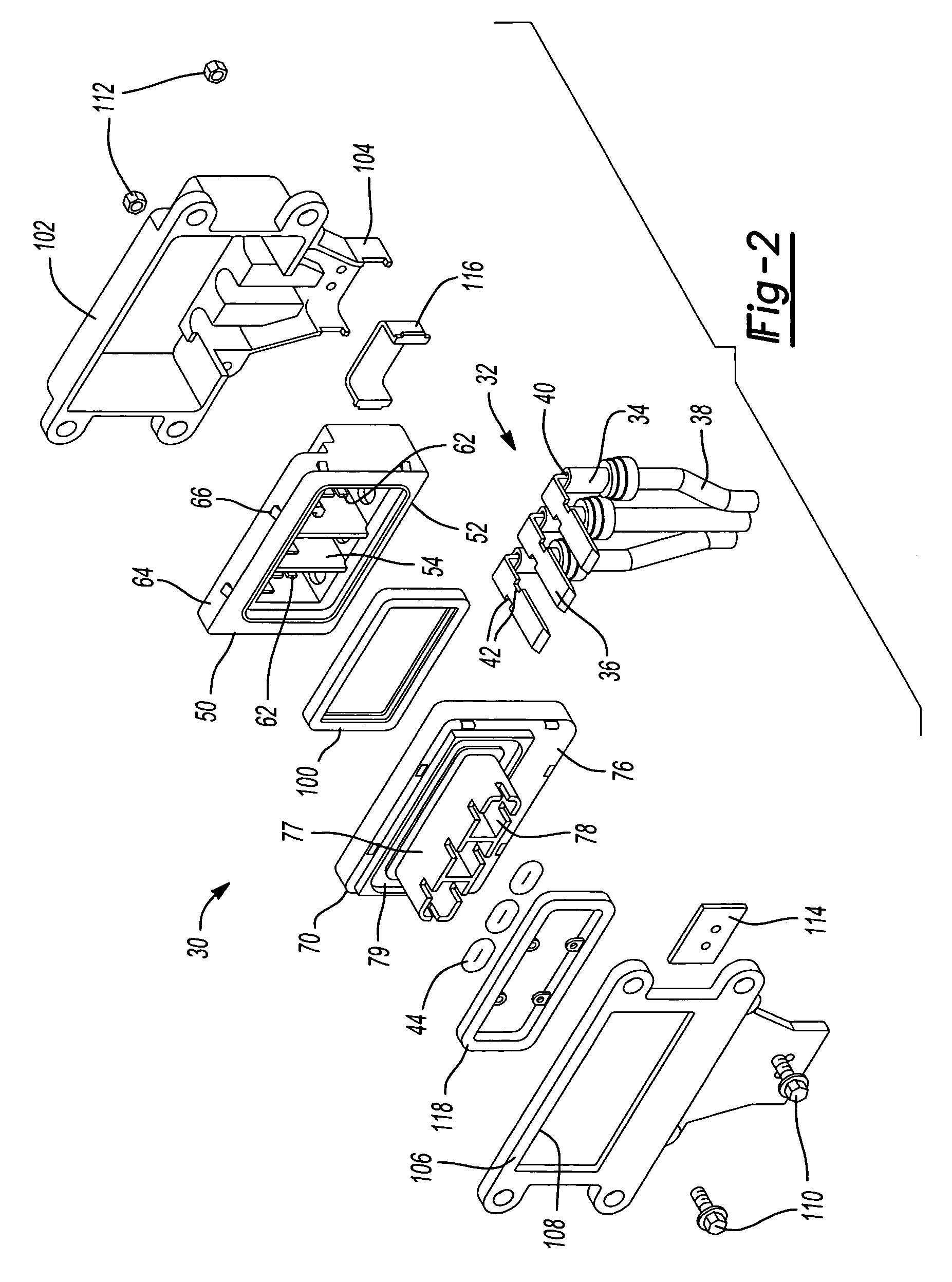
[0017]Referring now to FIG. 2, a connector assembly 30 according to the present invention is illustrated in an exploded view. The connector assembly 30 is meant to receive and secure right-angle or ninety degree electrical terminals 32. Each terminal comprises a wire-connect portion or segment 34 and an electrical mating portion or segment 36. The mating segment 36 is illustrated for example purposes as a male contact blade, but may alternatively be a female receptacle depending on the connector assembly design and function. The wire-connect segment 34 is crimped or mechanically and electrically attached by some other method to an electrical wire 38. The electrical mating segment 36 extends at a right angle from the wire-connect segment 34. The wire-connect segment 34 has protrusions 40 the purpose of which will be later described. The mating segment 36 includes notches 42 on each edge for receiving small, resilient o-rings 44 to help seal the wire connection from water and other co...


PUM


Abstract

A connector assembly has a first part with an interior for receiving right-angle electrical terminals through an insertion end. Wire-connect segments of the terminals seat within cradle-like members aligned in sets of rows extending across the width of the interior. Electrical mating segments of the terminals extend perpendicularly from the wire-connect segments. A second part of the connector assembly has chambers for receiving the mating segments of the terminal and a compartment with inner cradle-like members aligned in sets of rows across the compartment. The cradle-like members of the first and second parts are arranged to correspond in position to each other when the second part is assembled on the first part so the wire-connect segments are clamped within the cradle-like members, reducing vibrational and other motion of the terminals within the assembly.

Description

BACKGROUND OF THE INVENTION[0001]1. Field of the Invention[0002]The invention relates in general to an electrical connector for housing right-angle electrical terminals and more particularly to a connector with internal features for reducing movement of the terminals after assembly.[0003]2. Discussion of Related Art[0004]Electrical connectors in vehicles are subject to vibration and other motion caused by vehicle movement. Cracking in the plastic connector parts and dielectric failure of the electrical connection are possible if the motion is not controlled. Attempts have been made in the art to reduce motion of the terminals. FIG. 1 illustrates part of a prior art electrical connector 12 for receiving right angle electrical terminals 14. The terminals 14 have wire-connect segments 16 attached by crimping or other methods to electrical wires 18. Electrical mating segments 20 extend at ninety degrees from the wire-connect segments 16. The terminals 14 are limited in movement within t...

Claims


Application Information

Patent Timeline
Patent Type & Authority Patents(United States)
IPC IPC(8): H01R13/648
CPCH01R13/502H01R12/712H01R13/533
Inventor ADVEY, ALEXANDER J.HASIJA, JOHN J.TESFAY, SEMERE T.CHIDAMBARAKRISHNAN, RAJESH L.
Owner YAZAKI NORTH AMERICA
Why Eureka
Try Eureka