Localized plasmon resonance sensor

a plasmon resonance and sensor technology, applied in the field of localized plasmon resonance sensors, can solve the problems of difficult to improve the sn ratio of the sensor, the sn ratio of the localized plasmon resonance sensor is liable to be adversely affected, and the line width (half-value width) of the localized plasmon resonance spectra as that of the group of metal structures is broadened, and achieves high sensitivity

Inactive Publication Date: 2009-10-06
CANON KK
View PDF6 Cites 10 Cited by
  • Summary
  • Abstract
  • Description
  • Claims
  • Application Information

AI Technical Summary

Benefits of technology

[0012]A specific object of the present invention is to provide a localized plasmon resonance sensor capable of detection with high sensitivity.

Problems solved by technology

However, in the localized plasmon resonance sensor proposed above in JP-A 2000-356587, in the case of detecting an antigen-antibody reaction, the following problem has arisen.
For this reason, it is difficult to improve an SN ratio of the sensor, so that the resultant localized plasmon resonance sensor is liable to be adversely affected by a production error of the metal particles and a measurement error during detection.
However, in an actual localized plasmon resonance sensor, a group of metal structure is used, so that a large number of different localized plasmon resonance spectra are copresent in mixture due to an irregularity in structure resulting from the production error.
As a result, the resultant localized plasmon resonance sensor has accompanied with such a problem that the line width (half-value width) of the localized plasmon resonance spectra as that of the group of metal structure is broadened.
As a result, the line width (half-value width) of the entire resonance spectrum is liable to be considerably broadened, so that it is difficult to improve the SN ratio of the localized plasmon resonance sensor, which his also liable to be adversely affected by the production error of the sensor and the measurement error during detection.

Method used


Image

  • Localized plasmon resonance sensor
  • Localized plasmon resonance sensor
  • Localized plasmon resonance sensor

Examples


Embodiment Construction

[0022]The present invention has been accomplished on the basis of the following findings.

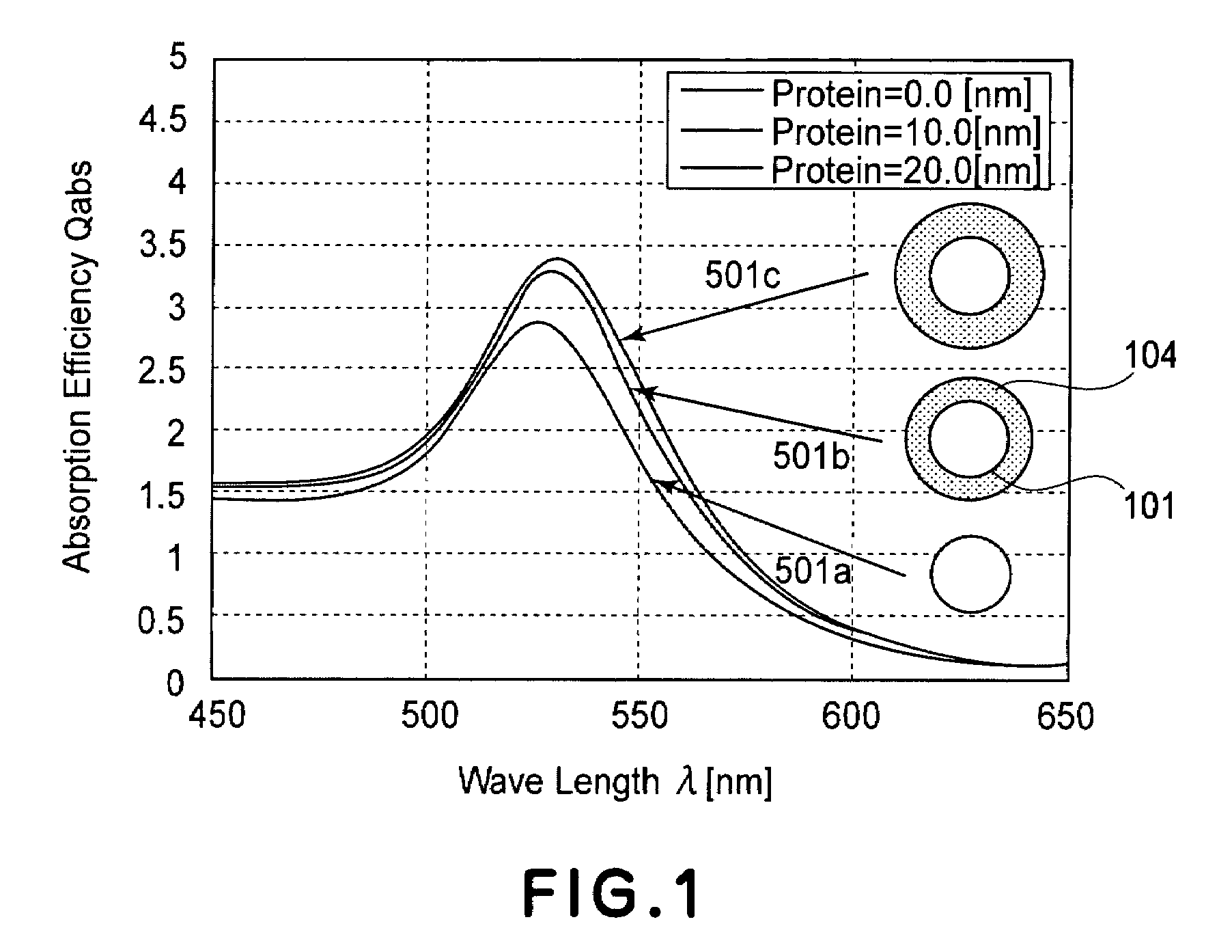
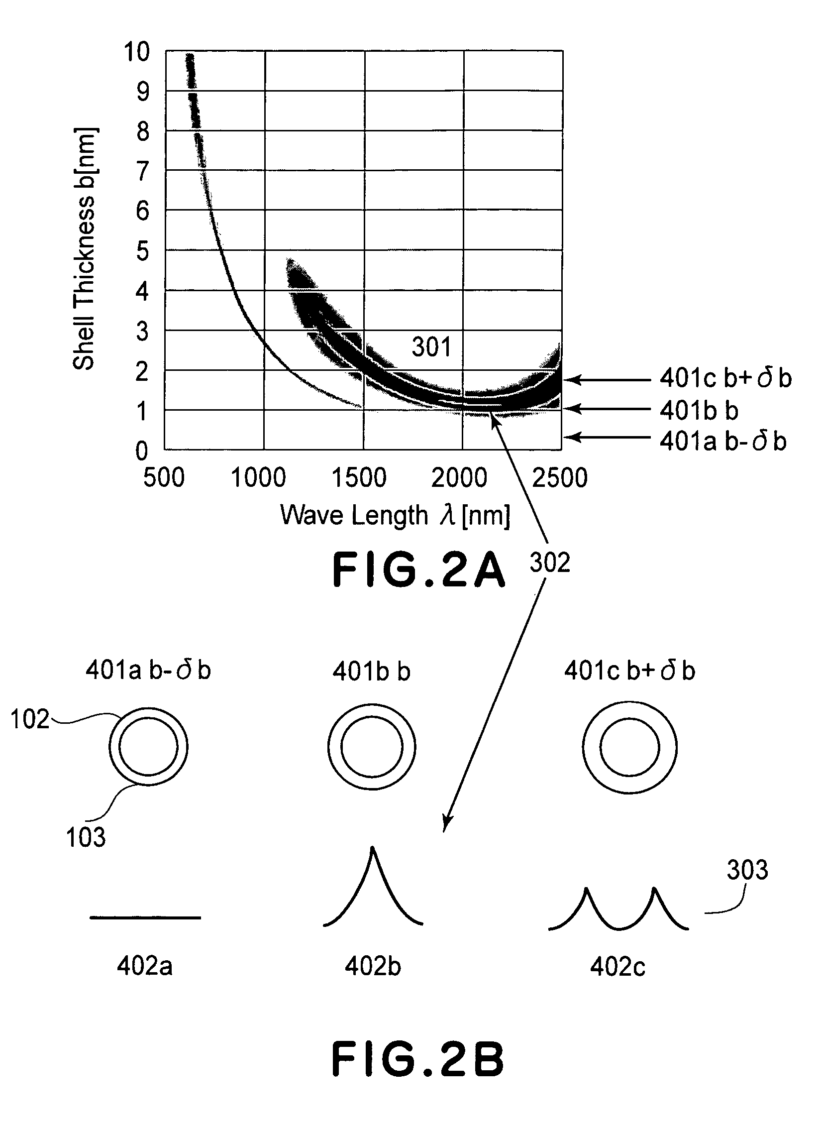
[0023]As a result of study by the present inventor, it has been found that there is a metal structure exhibiting a pair of a resonance peak which is shifted to a longer wavelength (red shifted) and a resonance peak which is shifted to a shorter wavelength (blue shifted) in an absorption spectrum when metal nanoparticles having a shell structure, prepared as a structure comprising metal (i.e., metal structure) used for a localized plasmon resonance sensor, are changed in structure. In an ordinary localized plasmon resonance sensor, the pair of the resonance peak which is red shifted and the resonance peak which is blue shifted is not used for the sensor.

[0024]In the present invention, a change of the pair of the red shifted resonance peak and the blue shift resonance peak in the absorption spectrum is detected and used for the localized plasmon resonance sensor, so that it is possible to improve ...


PUM

PropertyMeasurementUnit
refractive indexaaaaaaaaaa
wavelengthaaaaaaaaaa
thicknessesaaaaaaaaaa

Abstract

A localized plasmon resonance sensor for detecting a change in optical constant uses a structure including metal. In a response spectrum with respect to light incident on the structure, there are at least two resonance peaks including at least one resonance peak shifted to a longer wavelength side and at least another peak shifted to a shorter wavelength side, by the change in optical constant.

Description

FIELD OF THE INVENTION AND RELATED ART[0001]The present invention relates to a localized plasmon resonance sensor for detecting a chemical substance, a chemical reaction, a living body, genetic information, etc. The present invention also relates to a sensing method using the localized plasmon resonance sensor and a particle for use with the localized plasmon resonance sensor.[0002]In recent years, as a sensor capable of detecting the chemical substance, the chemical reaction, the living body, the genetic information, etc., a localized plasmon resonance sensor has been developed. The localized plasmon resonance sensor utilizes a localized plasmon resonance phenomenon caused by an interaction between conduction electron and light in metal. More specifically, the localized plasmon resonance sensor detects a change of a minute area of several to several tens of nm in a neighborhood of a surface of a metal structure so as to permit detection of the chemical substance, the chemical react...

Claims


Application Information

Patent Timeline
Patent Type & Authority Patents(United States)
IPC IPC(8): G01N21/55
CPCB82Y15/00B82Y30/00G01N21/554G01N33/54373G01N2021/0346G01N21/05
Inventor FUKUDA, KOICHI
Owner CANON KK
Why Eureka
Try Eureka